Showing posts with label jarrah. Show all posts

Friday, July 26, 2013

A Staircase Saga, Part 4. The Short Flight.

Some months after the Big Flight was installed, the time had come for the Short Flight to be added. Much had happened in that period, including the installation of the underfloor heating, the laying of the jarrah floor over the top, the building and defining of the new wall and the opening in the upper floor, the plastering and gyprocking of walls and ceilings, and more. With the plastering of the walls completed and now dry enough, I was looking forward to working on the stairs again.

This staircase will have two sets of winding treads, separated by a pair of normal straight treads - which I shall refer to here as the Short Flight.  Above the second set of winders will be the Big Flight. Below the first set of winders will be a couple of straight treads which will give a sense of "spilling out" into the hallway, wrapping around to meet the wall on either side of the staircase. Of course, then there's the handrail and the ballustrading upstairs! There's a way to go yet before this staircase saga is completed...

Back to the drawing board.
What a surprise! The actual measurements were checked against the original drawing, including the position of the tenon on the bottom of the Big Flight's inner stringer. This tenon would be fitted into the newel post which would be fitted around the wall in the opening of the wall.
The original full scale drawing.
Essential to the short flight is the three newel posts which are part of this component of the staircase. The drawing above shows the relationship between these posts, the wall through which the stairs pass, the two sets of winders, the big flight, and of course the short flight of two straight treads.

Making the newel posts.
The only way to get 90 x 90 mm jarrah is to recycle old verandah posts, obtained from Salvage yards.
Buried under layers of old paint, it is a lucky dip until the material is machined up.
Amazing how many nails and screws are lurking under the layers of paint on the verandah posts.
Two of the three newel posts required for this section will have a 30x30mm rebate out of them to fit around the wall snugly, through which the staircase will pass.
One part of the full scale drawing of the three newel posts and how they relate to the short stringer and the wall.
The Handrail.
A short section of handrail/balustrading will extend between the two lower newel posts. My customer found a profile she liked on a US website, so I did some experimentation to see if I could get close. I found I could get close starting with 60x60mm material, the table saw, and three different router cutters! This profile will be used for all of the handrails to be added later. I made the short section I would need for this short flight section.
The handrail profile... and how to make something close!
The balustrade panel.
Between the hand rail, the stringer and the posts either side, would be some balustrading. While discussing  the design possibilities, we hit on the idea of matching the original entry hallway woodwork adjacent to the staircase. Brilliant! I grabbed a piece of drawing paper and a ladder, and did a tracing of the original tulip panel.
The original decorative woodwork above the hallway.

Tracing the tulip panel
The tulip design was cut out and then used to draw around on the jarrah panel.
I don't use my scroll saw often, but it's great for jobs like this.
The panel was made! What a good idea. Time to put it all together.

Putting it all together.
Using the full scale drawing, all the components were cut to size and angle, the mortises chopped, the tenons cut, and every joint test fitted. Time consuming, but essential before doing a dry run cramping it all together. If it is all sweet, it will be disassembled and then glued up in situ.
All these angles are very tricky to cut and fit. I'd be lost without the full scale drawing to take measurements off.
These two posts straddle the wall. The narrow panel will hide the wall end between the posts. 
Looking good for the test fit.
With all the components and joints fitted, it was time to bite the bullet. Glue-up time, on situ.

The glue-up begins, That's the hole in the wall we are going through.
The short flight starting to take shape.
The short flight develops further.
Another view. That's the big flight up around the corner.
Another look. Yep, the tulip panel was a nice idea!
Gluing all this up was a huge job. The upper post had the big flight's tenon housed into it as well as the nose of Tread#11. It had to be fitted around the wall, and the treads and  a couple of risers put in place - as well as the balustrading/handrail, etc. All in all, I was very pleased the way it all came together.

The short flight was now in place. The next step would be to build the two sets of winding treads, which go either side of the short flight.

Sunday, July 7, 2013

A Staircase Saga, Part 3. The big flight.

The staircase I am building completes it's ascent with a big straight flight, with Tread Nos 11 - 20. The whole staircase will be a very functional and beautiful feature in an 1930's Art Deco home which is being renovated. Lucky me ...  I am blessed with the task of providing a significant amount of the carpentry, joinery, and cabinetwork within the building. It's such a privilege!

The planning process is outlined in an earlier post: A Staircase Saga, Part 2. Getting Started. Having done the planning, then bought and dimensioned the stringers, it was time to get stuck into building the big flight. This would be the first part of the staircase build, as it would determine the position of the opening on the top floor. It would need to be in place before the plasterers and gyprockers could do their thing and would become part of the structure of the building once everything had been built around it. It would be in place for some months before the rest of the staircase could be completed.  It was also going to be very heavy!

I started setting out the treads and riser-board positions on the stringers. With these drawn in place, I then made up a couple of jigs for the router to enable accurate housings to be consistently cut.
The tread housings were cut by the router using a purpose made jig.
The pair of stringers with tread housings completed.
A different purpose made jig was used for cutting the riser board  housings.
With all the housings cut, it was time to fit the treads and riser boards. 
Making the treads. The intention was always to recycle the old jarrah rafters from the original roof into the treads. The rafters were docked oversize, scrubbed with a wire brush, scanned with a metal detector and de-nailed as required. I then machined the material, flattened and dimensioned the sticks to 47mm thick and as wide as possible for each individual stick. Suitable wider boards from the roof timbers would be machined to create the riser boards, finishing at 18mm thick.
Rafter sections (right) cleaned up ready to be machined, and potential riser boards (left). 
Three treads simultaneously glued and cramped.
A 1/4" plywood spline, 25mm (1") wide, was inserted full length in each join in the treads, and epoxy glue was used for the joints. It worked out mostly at 3 rafter pieces per tread. When the glue was dry, these treads were machined to the required 45mm thickness.A finished tread depth (width) of 282mm was required for each tread. The riser board face sits 16mm (5/8") behind the  nosing of the tread, so I machined the required groove on the underside of the treads, ready to take the tongue (a barefaced tenon) on the top of the riser boards. The noses of  the treads were rounded over with a 1/4" radius rounding-over router bit.
With the treads, risers and stringers prepared, it was time to put it all together. Well, it was going to be too heavy to put together in my workshop and deliver to the site - so it was going to have to be assembled on site. Each of the joints was individually test fitted at my workshop, then all the components taken to the building site ready for assembly.
The test fitting of the treads and risers in full swing.
View of some tread ends, showing construction with plywood tongues in the joints.
Lookin' good... from the back of the stairs.
The big flight was glued and assembled on site, on a pair of sawhorses right below the opening in the floor above, and then two chain blocks I had rigged were used to lift the big beastie into place.
Much careful planning by way of a scale drawing of the wall.and floor joist structure at the top end, and the preparation of the top of the stringers had been undertaken during the construction of the stringers, which enabled the stringers to be parked on the top of the wall plate when the top flight was lifted into position. While getting it all up there was a challenge, it finally went beautifully into place. It was a winner! Props were placed and secured, to hold the lower end in position, and several fixings put into the wall through the underside of the stringer against the wall. A couple of bolts through the top of the stringers into the floor joists, and the big flight was in place.

The next step was to build the wall on the kitchen side of the big flight, joining the outer stringer to the floor joists and ceiling above. Below this stringer and the big flight will in be the mini-laundry behind doors. The big Blackbutt posts framing the laundry area would also serve as the props for the outer stringer.
The upper wall frame being built around the top flight.
The big flight was in place. Nothing else would happen on the stairs for a few months, until the other trades had completed all their work around the big flight and the openings top and bottom and through the wall.

Great to see once again how careful planning and preparation has once again paid off.
While I had plenty of other tasks to get on with around the building site, I would be looking forward to getting back onto the stairs again downs the track...

Sunday, June 16, 2013

A Staircase Saga, Part 2. Getting Started.

This a bit like the Star Wars movies saga. The first post I did on this Staircase Saga came midway through the story, and now we have gone back to the beginning with this, the second post!

Getting started.
First you need somewhere requiring a set of stairs. My customer has been doing a renovation on her lovely Art Deco double brick and tile home from the 1930s. This has involved extending out the back and going up - putting on a second storey. Hence the need for a staircase!  I have the plans, but plans are always theoretical. There is never the level of accuracy that you need for building a staircase in a defined and confined space. The architect has the basic idea on the plan, but my task is to convert the concept to reality, in conjunction with the customer's ideas and preferences.
A photo of part of the architects' building plan.
The concept. 
These stairs would start in the hallway with treads 1 & 2 leading to a set of winders (Winding treads go around a corner, radiating out from the corner newel posts, making them wedge shaped). Treads 3,4 & 5 would be winders taking the stairs around a 90 degree turn. Treads 6 and 7 would be straight, linking this first set of winders to a second set of winders. Winding treads 8, 9 & 10 would then take us through another 90 degree turn, with treads 7 and 8 taking us through an opening in the wall into the kitchen/dining room. At this point the second set of winders would connect to a long flight consisting of treads 11 through to 20 (where tread 20 is the top floor level). A compact laundry would be built  under the long flight, concealed behind doors, and a wall built above alongside the long flight. Thus there was no connection between the stairs and the kitchen/dining/laundry area. The whole staircase is therefore U-shaped, with one leg longer than the other. It would also be a challenge to build... and I love these kind of challenges.
 
The top and bottom floor plans in the pics above give further info about the proposed layout.

Materials.
The stairs were to be built using Jarrah, using as much of the original materials as possible. As was the norm in Western Australia for over 150 years, all the construction timbers in the house were jarrah, with a little bit of Karri. Modern carpenters & builders do not like using old jarrah. They love treated pine and LVL as it is light, easy to work, consistent in dimensions, and nail guns offer little resistance. So while the original roof timbers were removed to make room for the second storey, they were not re-used. Treated (CCA) pine was used for wall and roof framing upstairs. The old jarrah rafters and other roof timbers, which had been seasoning in the original roof for over 80 years, would be used where possible for building the staircase and for other joinery tasks around the house. The old house being recycled into the new parts of the house. Nice.
Sections of the rafters (4"x2") and ridge pieces (7"x1") docked oversize ready to be dressed.
The 4"x2" rafters would be docked, dressed, glued up and machined to size to make the stair treads. Any wider boards,  like hanger beams, would be used to make riser boards. Great to be recycling the removed original roof timbers back into the house as part of the staircase.

Planning the staircase build.
Walls were being rearranged, but there was enough detail available to take some initial measurements.

1. The overall TOTAL RISE has to be established. That is, the total height of the staircase. The vertical distance from the lower floor level and the top floor level. This was measured as 3650mm. Divide this by 20 treads, and you get 182.5mm. This is known as the RISE. This will be the measurement from the top of every tread to the top of the next tread. At many times during the building of the stairs, it will be helpful to have a Riser Story Stick - a straight narrow stick long enough on which to accurately mark off and number the position of every tread along it's height. A very handy tool!

2. The GOING has to be established. The Going is the distance from the face of one riser to the face of the next. Add all these together and you have the Total Going. By measuring the space available, we want to see that the total distance divided by number of treads will fit into the space within certain geometric parameters. Somebody once worked out that it takes twice as much energy to step up than it does to step forward, and this is used in establishing the relationship between the rise and the going.
Under the Building Code of Australia, staircases are required to comply with the parameters and formula in the table below. Working all this out is more complex when there are winders, but I calculated that the Going on the straight treads would be 265mm. This fits within the Code. If it didn't fit the formula range, then the Going or the number of treads (the Rise) would need to be changed until the formula complies. Adding a 15mm nosing to each tread, the stair tread depth (front to back) on the straight treads would be 280mm.

The Building Code of Australia says:
STAIR RISER AND GOING DIMENSIONS (mm)

Riser (R)Going (G)        Slope relationship
                (2R+G)
MAXMINMAXMIN         MAXMIN
Stairs (other than spiral)190115355240          700550


3. As accurately as possible, I transferred the measurements of the space available onto a  2.4 x 1.2m (8'x4') sheet of MDF, to create a full scale drawing (birds eye view) of the bast of the stairs. The treads, nosings, newel post and stringer dimensions, etc, would all be drawn onto this sheet, to ensure that it all fits. By doing this very accurately, this drawing could be used in order to measure and cut component parts as the build was taking place. An important reference item, this drawing would be, throughout the build.
One of the drawing boards, planning the winder and newel post positions.
4. Another sheet of MDF was used as a drawing board to do a full scale drawing (side view) of the top section of the long straight flight. This would be used to resolve the matter of the top of the stairs and the way they would connect to the top floor joists and or the wall. Using a full scale drawing would allow the planning and construction matters to be resolved and the components to be cut ready for installation. The final top tread's nose position also needed  to be resolved, to ensure the staircase would not terminate too close to the bathroom wall/door on the top floor. Sorry, I don't have a good pic of this drawing.
Not the accurate drawing... this one I did roughly on the wall! Resolving the top dimensions... 
The top tread would be made 130mm wide, as this matches the width of the jarrah floorboards to be used on the top floor. The rough wall sketch above was part of my thinking in pictures. I often do that... The big drawing was where I planned the way the top of the bight flight would be supported and connected. Sorry, no pic.

5. Another drawing! Yes, another full scale drawing was done on another sheet of MDF, showing the relationship of the three lower newel posts to the wall through which the staircase would pass, and where the treads would come in relation to the two short stringers supporting treads 6, 7 & the nose of 8. This was all going to be very tricky, so careful planning would be required. A full scale drawing is sometimes the only way to figure this out and create components with housings and tenons which will fit together perfectly.
You can't beat an accurate full scale drawing to work things out.
With all that planning, involving lots of mathematics, drawing, head scratching, and general cogitating there shouldn't be anything which could get in the way of it all coming together perfectly, should there?

Interestingly, step 5 would not be able to happen until a whole lot of other building work took place first - including the hole being cut in the wall through which the staircase would pass. Only then would those critical measurements be checked and confirmed. Like many of these older houses, things are not normally square, plumb or level. Oh well, that's all part of the fun with these gigs...

OK. Time to stop talking and start building!  The first task would be to build and install the long top flight.

The build begins!
The stringers for the long top flight would have to be bought new, as there was none available or suitable in the salvage yards I'd checked out. I dug through the limited pile of pre-dressed 10"x 2" jarrah sticks at the timber yard, and fortunately was able to find two which were long enough and straight enough. The longest one of these was 4.5m (15 ft) long - only just long enough for the outer stringer. Gee they were heavy!
Serious money in these two boards. Now I'm committed!
With the sticks loaded on the ute, I drove straight to someone else's workshop with the machinery big enough for me to flatten, straighten and thickness the big stringers to the required dimensions. They wouldn't fit in my little workshop or over my 6" buzzer! It was also a two people job. Once the basic machining was done, the sticks were loaded back onto the ute and I took them home to start setting out the housings for the treads and risers.
The building of the staircase had begun...

Friday, May 6, 2011

External Stairs from Recycled Timber.

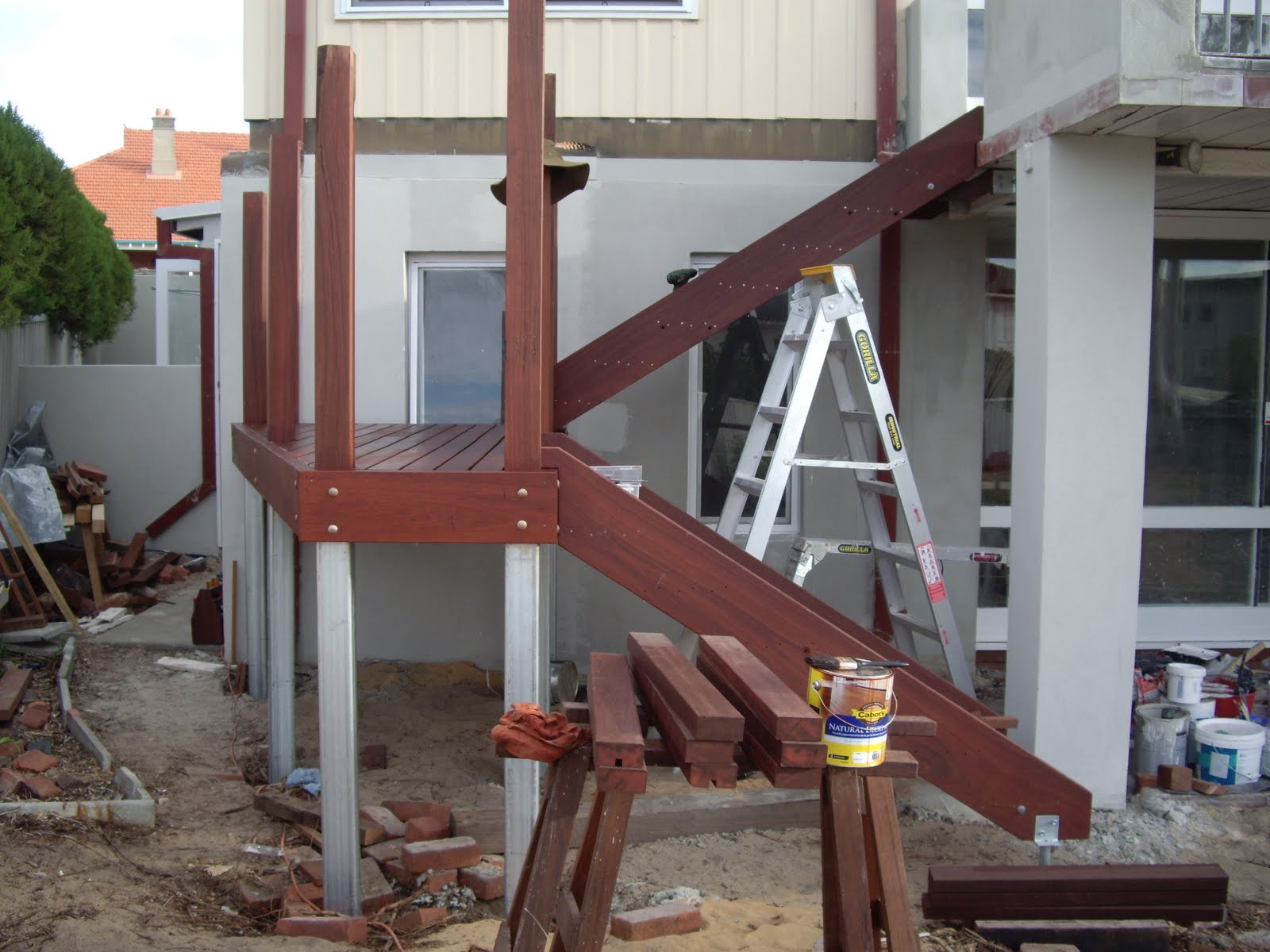
Aahh!... another set of stairs...   Amid all the different types of woodwork I do, what I enjoy about building stairs is the brain challenge they provide - particularly in the planning and setting out phase. One of my latest jobs has been to build a set of external stairs for a client. The task was to plan and build a set of stairs which would fit into a particular space on an existing building which was undergoing significant renovations. The stairs would comply with the Building Code of Australia, and made primarily from recycled jarrah.
That's the space available to build the stairs ... in front of the red brick wall.
View from the top looking down. The structure would have to keep 1.5m off the fence line.

Planning the job.
Having taken measurements on site, it was then down to the planning stage - which always involves doing scale drawings on my trusty drawing board. I have never got into CAD drawing on the computer. I still like the old "Technical Drawing" techniques using a T-Square and pencils on a drawing board.
The first place to start with planning a set of stairs is to know the total Rise - the distance from the top floor level to the bottom ground level. In this case, allowing for the new ground level which will be built up to the same height of the underside of the back door sill, the total rise will be 2.5m. This divides readily into 15 steps, each with a rise of 166.67 mm. That rise fits within ergonomic convention. The next thing to determine is the "Going" - the horizontal depth of each step from nosing to nosing. The accepted rule is: (2 x Rise) + Going = 585 (or up to 625mm.)   I decided to have a Going of 260mm, which fits within the range OK.
With the Total Rise, the number of steps, the Rise and Going all established, the length of the flights can be determined. Drawing this to scale would give me the angle of the stringers and help me to visualise how it will fit within the space. A landing will need to be included, as this divides and separates it into two flights going in opposite directions. There also had to be the required minimum standard headroom where the lower flight approached the ground while coming under the top balcony.
After a lot of drawing, calculating, brain-waves coming in the dead of night, meetings with the client and 3 drawing versions later, I believed we had hit on the answer of how to make it fit in the space available and my client was happy too.

Gathering the timber and starting the construction. 
The treads would be easy. Three sticks of timber dressed to 90 x 45 (and nearly 900 long), with gaps of 8mm between, would give a stair tread of  286. With a 260mm Going, there would be a 26mm overhang of the nosing over the back of the tread below. Nice. These sticks would be ex 4"x2" jarrah. In domestic buildings these were normally used for floor joists, rafters and often ceiling joists. Much of the 4"x2"s I had in my stocks came from a house built in 1930. After seasoning for 80 years, this stuff is dry!

4" x2" material cleaned up and ready to be machined to size.
  As much as possible, gum veins were avoided in the selection process, the timber docked just overlength, de-nailed, scanned with a metal detector, scrubbed down with a wire brush, straightened and squared over the buzzer, and machined to the required 90 x 45 through the thicknesser. Three of these per stair tread.

The stringers were a problem. After searching round the salvage yards, I would be unable to find the jarrah suitable to make the stringers. (Stringers have the treads housed into them and make up the sides of the stairs). So I had to buy the material new. The required 10" x 2" jarrah I purchased was pre-dressed and what they call prime grade. Scary stuff really, as I had to pay over $650 for the 4 sticks I would need in order to make the 2 pairs of stringers! Ouch!

The decking would be easy. By ripping 4"x2" jarrah sticks down the middle, the two halves are each machined to 90 x 20mm.  A number of these I was able to make at 3.2m long, enough to go the full length of the decking. The arrisses were shot off with a block plane, and the decking boards pre-coated with oil.

A 4"x2" piece of jarrah ripped down the middle and opened out. Fantastic colours and interesting nail holes coming in from the edges. It will be machined into beautiful recycled jarrah decking. 
  The top plate or apron of the landing would be ex 8"x2" jarrah, dressed to about 45 x 190mm, and the landing floor joists were ex 6"x2" jarrah from salvage. The landing would be supported by 6 galvanised steel legs set in concrete, and the jarrah posts above would be machined to 100x100mm. These took a lot of hunting down - from salvage yards and other sources. I was fortunate to get 4 posts from an old 6"x6" jarrah power pole! The 120 x45mm handrails would also be obtained from the 6"x2"s.
All nails and other fixings used would be Hot Dipped Galvanised. The finish to be applied to the finished timber would be Cabot's Natural Decking Oil.

The construction process started with making a set-out board of the stringers, giving me the angles and dimensions of the tricky ends of the stringers. This info was then transfered on to the stringer material and the two pairs of stringers were then made at my workshop and pre-finished with a couple of coats of oil.
The Stringers were laid out in pairs, marked out, and the tread housings cut.
The treads were then all made and cut to size ready. The two flights would be too heavy to lift if assembled, so I decided to do the assembly on site. With the flight components made and the landing materials organised, I moved to the site to build the landing. When the setting out on site was completed, the holes were dug for the steel posts. Using lots of big cramps and big sticks of timber, all the prepared posts were suspended in their holes, plumbed and held in the right positions. My son Ben was giving me a hand that day, and it was a big day! Ben operated the electric cement mixer and we did the concreting job. Six posts, rock solid. The following day I would do the concreting of the final two, supporting the base of the lower flight.

One of the steel posts suspended and cramped in position in its hole, awaiting the concrete.

The top stringers were also suspended/supported  in place to ensure the landing position was correct. While working from the drawings, sometimes it is good to check "in the flesh". 

The lower flight stringers fixed in place, with metal spiggots at the base set in concrete. The concrete will later all be buried under sand and brick paving.
 Completing the landing.
With the steel posts set in concrete and the landing apron or top plate being bolted to the steel as the jarrah posts were inserted into them, the floor joists were then added. These in place, the decking was then nailed down.

Decking nailed down and completed. That's a cake of soap on the stair tread - to lubricate the 4" galvanised nails used in landing construction.

Top flight treads fitted in place. Handrails and balustrading still to be added.

Landing done. Stringers in place, most treads installed. Time to cut posts to height and add balustrading. 
The jarrah posts were installed "over-long", so that they could be cut to a finish height after the transitions had been worked out - ie. where the flight handrails meet the landing handrails at the newel posts. These transitions would be calculated and modified ensuring a smooth transition as well as compliance with the minimum requirements under the Building Code of Australia (except for the lack of infill under the balastrading, which someone else would be doing.) While the scale drawings would give a good indication, the measuring and marking of the real thing in place would be most accurate. 

Making and Fitting the Handrails.
With the landing decking completed, it was time to get on with the handrails. The customer hadn't quite decided what balustrading to have - but will probably have stainless steel horizontal wires. That's someone else's job. Other than the posts below, I don't do steel. Out of interest, to comply with the BCA, balustrading must not be able to have a 125mm (5") sphere pass through any part of it. Horizontal handraisl must be a minimum of 1000mm high, etc. At the commencement of the job we had agreed I would only to install the newel posts and handrails, so that was what I was doing. I had made the handrails from ex 6"x2" jarrah ceiling joists. Nice straight sticks too, which I had machined into 120 x45mm. This gives a 10mm overhang on each side of the 100mm posts.
One of the newel posts at the transition from landing to top flight. That's the tenon on top awaiting the handrail which will be housed onto it.
The posts were cut to length with tenons on top, and the corresponding housings cut in the underside of the the hand rails. The interesting part was the angled corners of the landing handrails. In one of these brainwaves I have in the dead of night, I resolved how to do the joint... a beautiful mortice and tenon joint. In fact, a stub tenon with a haunched tenon either side of it. And it worked a treat!. All this was done on site. My trusty tenon saw cut the tenons on top of the all the posts, and the tenons on the ends of the handrail returns on the landing. Good to see a saw live up to it's name. I was going to take photos of the joint components before I glued it up and fitted it to the posts ... but once again I was so hooked into what I was doing that I forgot and just assembled and glued the joint. Sorry about that...  Love that glue - Titebond III.

Nice mortice and tenon joint! 27 degrees off 90. There's a long haunch and a stub tenon in there.

That's the other corner. Another very tidy joint, the same as the other end.
Anyway, I was very pleased. The haunch mortice was cut with a slot cutter in the router, and the deeper mortice for the stub tenon was chopped by hand. The tenons were all cut by hand. It was a winner.

Job completed.
When I had completed construction, I brushed the whole structure down and gave it one more final coat of the oil finish. It looked like a million dollars. I then gathered up my tools, cleaned up the site, took a few pics, and drove away. Satisfaction is such a nice warm feeling. Here's a few pics:


View from the top looking down and across.

View down the top flight.

View of the bottom flight from above.

The ground level is yet to be built up and brick paved. The height of the bottom step allows for this. 

This pic puts the stairway in context. Soon there will be a swimming pool in the foreground!

View from the ground level back door.The galvanised steel legs will be painted a colour similar to the jarrah. 
On the joys of jarrah.
Jarrah is such a beautiful timber, and I am lucky that I have been working with it all my life. Jarrah (Eucalyptus marginata) is only found naturally in the southwest of western Australia. I understand there is only about 6% of the original forest remaining. Such a significant timber since European colonisation began here 1829. Until a couple of decades ago, in Western Australia just about every part of a timber framed house from the stumps to the ridge piece were all made from jarrah. It is a is very strong structural timber, very durable in the weather and in the ground, and a very high quality furniture material. Beautiful grain and rich reddish brown colours. The all round dream timber. Yep, I love the stuff.

Much of this stairway was made from recycled jarrah. This material had come from an assortment of buildings and other uses, much of it from a house which was built 80 years ago. All over it, there are the echoes of the former lives of this timber. Rows of nail holes along a tread nosing, testifying to a past life as a floor joist, with the nail holes even showing the width of the old floorboards which were once nailed to it. A couple of old checks in the side of a newel post, speaking of a former life as a verandah post on a building. The residual jaw marks from an old pair of floor cramps, telling of the time that piece of stair tread was once a floor joist. Other pieces were once rafters or ceiling joists, and the spacing of nail holes can often speak of these former lives. It is the echoes of the former lives of this timber which is so fascinating in something made from recycled timber. It is also why I don't fill the old nail holes. Let them speak.

Working with pre-worked timber also gets me thinking about the tradesmen who worked this timber when it was green. That's how these building were always constructed. Green jarrah, while heavier, is easier to work with - and easier to nail. No need to pre-drill the nail holes like I had to! These guys built the houses only with hand tools. There were no power tools. Most of the saw mills were steam driven, and life was different. Simpler times, moving at a slower pace, when tradesmen took pride in their tools and their work. It wasn't just about money and having a job - it was a vocation. An identity. A way of life.

I tip my hat to those guys, and hope I did them proud in the way I re-used the timber they first worked.