Wednesday, February 22, 2012

New life to a 1930's kitchen cabinet.

I have recently been rejuvenating an old kitchen cabinet. Most people would have tossed it out, but my customer wanted to have it as the sink cabinet in her kitchen as part of her house renovation. While it just oozes with character and history, it also required a serious amount of work to bring it back to life. The cabinet came out of a house in Wembley which was built around 1934. During the 1980's, a new kitchen was installed, and the old cabinet went outside to become a potting table in the garden. There it stayed and was used as such for many years. The weather was not kind to it. When I first saw it at it's new home in Fremantle, it was awaiting some serious attention before it could be installed.
The cabinet door latches were too heavily rusted to be salvageable...
A classic piece of Western Australian history.
What a mug! I forgot to get a photo before I started working on it. It is truly a classic piece of Western Australian 1930's construction. So here is a description: the cabinet was clearly made on site by a carpenter from materials used in the construction of the house. It was part of the role of the carpenter.

The cabinet is nearly 6 foot long, 18 inches wide, and about 40 inches tall. Pretty tall! The shelves were made from jarrah tongue and groove floorboards. The frame was made from 3"x 1 1/2" jarrah. The two doors on the front, the end panels, and the cabinet face were made from 4 1/2" x 5/8" thick jarrah V-joint lining board - the same stuff which was used for the old "ledge and brace" dunny doors. The doors have two cleats on the back which the lining boards are nailed onto - and the nails are clinched over behind the cleats. The doors are hanging on T-hinges. The colour was Battleship Grey, though it seems an earlier colour may have been white or whitewash. An undercoat? It seems there was no other coat of paint ever applied to it. The backing of the cabinet was rough sawn boards of Yellow Pine, about 7" wide, edge butted together. The whole thing was held together with a variety of nails. The cabinet top was one of those old wooden ones. These were usually made from Kauri Pine or Hoop Pine. The enamel bowl would have been suspended underneath the hole in the sink top, and draining grooves were planed in the sink top radiating towards the bowl. Interesting to remember that once these wooden benchtops were normal. The cabinet was in a bad way, with most of the nails loose so the whole thing wobbled around. There was some rot in the shelving, in the base of the backing and the base of the cabinet ends. The top itself was very badly split from being in the weather for years. Most of the original top would not be re-useable for the benchtop.

Face down on a set of saw horses, the back has been removed.
The Yellow Pine backing boards, lined up in order. Plenty of rot at their bases.
The other wooden sink top, the spare one.
The rear of one of the doors. Note the clinched nails on the cleats.
In addition to breathing new life into the cabinet, it would also be modified so that it would fit into a recess behind the new cabinet position in the kitchen.

Steps to a new life for the cabinet.
1. The backing boards were removed. This enabled me to remove the rotten boards in the shelving, and replace them. The shelving was screwed down onto the cabinet frame.
2. I squeezed up the lining boards on the cabinet ends with sash cramps, at the same time as squaring up the ends. The lining boards were then re-nailed onto the end frames.
3. A new horizontal support was added under the rear base of the bottom shelf, to counteract the hammock shape of the bottom.
4. Additional stiles were added at the rear to accommodate the frame extension at the rear required to fit in the new kitchen location.
5. The cabinet was turned onto it's back, and the face firmed up. Too fragile to nail, I opted to screw the lining boards onto the face. Slotted screws were used, consistent with the era.
6. Using a big square and my 6 foot straightedge, a new top and bottom level was drawn onto the frame all round, and the I cut to these lines. By removing about 1/2" from the top and about 1" from the bottom, much of the rotten damaged ends of the lining boards were removed and the frame straightened up.
7. The new rear frame extension was completed, and the backing boards were shortened and re-fitted. Additional lining boards were used, from my stocks. These had come from a very old house in West Perth. Sometimes it is an advantage to be a wood bowerbird!
8. My customer wanted the old paintwork to be partly removed. So I removed the doors and used my belt sander, random orbital sander, and hand sanding to chew off the bulk of the paint. The result is very pleasing, and will eventually receive a clear coat of something -with echoes of the old colours coming through subtlely. Nice.
Removing the doors ready to clean off the bulk of the old paint.
The chosen level of paint removal. Mostly jarrah showing, but with echoes of the old paint coming through... 

9. Time to put the cabinet into position. Using the old fashioned method, I placed the cabinet in position, packed it up so that it was level, and scribed the based to follow the contour of the kitchen floor where it would now live.
10. The holes were cut in the back of the rear frame extension to take the waste pipe, water pipes and power point. With this done, it was time to fix the cabinet in its new position.
11. The frame was bolted to the brickwork behind. The doors were still to be re-hung, after new catches could be found, and probably after the plumber has been - to make access easier. Time to measure up for the top which needs to be made to replace the old one and extend into the recess behind.

The rejuvenated cabinet, with its new rear extension into the recess. Beautifully level.
Making the new top.
The original top was just too damaged to be usable in making up a suitable top - except for a strip along the front. My customer had another wooden top to toss into the mix, but it was not alot better. These tops were traditionally made from either Hoop Pine or Kauri Pine - though I do not claim to be able to tell the difference at this stage. My hunch is that the original top was made from Kauri Pine.  With the new top to be bigger (extending into the recess behind) and the timber in the old tops being to badly split and rotten, we decided to create a whole new top. I was able to obtain a new 3.0m (10ft) length of kauri pine which  was 250 x 75mm (10" x 3"). After ripping it down the middle, I was able to create two 10inch wide boards which were just over 30mm thick. From this I glued up the material for a whole new benchtop.
The oversized new top glued up, with epoxy resin this time.
My trusty Record No.0110 was used to clean off squeeze-out from the joints.

I gave the back of the sink top a sealing coat of Tung Oil/Orange Oil mix, and left it to dry a couple of days. I then took the top to my customers home to complete the sizing and fitting of the top. She'd had an old metal basin re-enamelled, so I would need to measure it carefully to be able to cut the hole in the benchtop.
The "bowl hole" cut out of the benchtop, but the top not sized yet.
Router jig used for cutting the drainage grooves. 
Making the drainage grooves was interesting. My Dad tells me the way it used to be done was a strip was pinned onto the sink top in the right position, and a moulding plane with a coving cutter was used to progressively cut each groove getting deeper as you approach the bowl hole. I did not have such a moulding plane, so I rigged up a jig for  a router trimmer with a coving bit. By making a track for the router which was tapered in elevation by about 7mm over a 600mm length, I was able cramp it over each drain position and easily cut the drainage grooves. It worked a treat!
Drainage grooves completed, and top cut to size. Now for a test fit!
After a couple of goes fitting the top to the brickwork surround while in position on the cabinet, it was time to do the final sanding and apply a coat of Orange Oil to the top. An hour later, I fixed the top to the cabinet frame.
Top now made, and first coat of Orange Oil applied. Looking good!
Top now fixed down to the cabinet frame.
Detail shot of the bowl edge and the drainage grooves.
That nicely re-enamelled bowl looks pretty good under the new sink top.
Job done. A new top like those which were common in the 1920's and 30's.
 I am particularly pleased the way the new top worked out. Lucky to be able to get some Kauri Pine which also happened to be quarter sawn. Ideal for the job. While the original top was just too degraded to be useable, there is a reasonable section of the front edge, about 5" wide, which could be re-cycled into breadboards for the kitchen. I've made the suggestion. The other top, the spare one, has a strip through the middle which is badly split. That could be cut out of it, and again I reckon the rest of the material is very recyclable. The decision to make a whole new top (and not to cobble together a mixture of the two old tops plus some new material) was a good one.
It's been a very interesting and enjoyable job to re-vitalise the old kitchen cabinet, and install it in it's new home. Although the top is new, the original cabinet from the 1930's has been given a new lease of life, extended to fit into the recess behind, and has pride of place in it's new home as the kitchen sink cabinet. The new top will soon look more aged through use, and down the track people will be amazed that such an old cabinet can be in such good condition! It also fits into it's new home very pleasingly. Once the plumber has come to hook it all up install the taps, we'll re-hang the doors. Might be worth an updated photo then, of the completed whole. Stay tuned for that one...

After the plumber, the doors will go back on. What a glorious renewal...
Thanks to my customer for seeing the potential in the rickety old kitchen cabinet, and for giving the the task and honour of bringing it back to life. That has certainly been done to great effect!

Tuesday, February 21, 2012

Making a Karibari Frame.

Have you ever heard of the "Batman Joint" in woodwork? Not until now... you see, for want of a better term, that is the name I called this joint used in the making of a Karibari frame.

Another interesting project! The paper conservators at the State Library of Western Australian wanted a karibari frame made up to particular specifications which they provided me. Mind you, the picture on paper of the corner did not make sense technically, so after a few goes at experimenting, interpreting the diagrams and comparing what I could find on the Internet, the Batman Joint was born as a solution.
The component on the joint which gave the Batman Joint its name.  
The material specified to be used was Western Red Cedar. It is light and stable, and resistant to mould and insect attack - but also very soft and cheesey to work. I was seeking to avoid any knots and keep the grain as straight as possible as I machined up the timber from the 3"x2" material that I bought to do the job. 

The completed Batman joint. If this is correct, then there must be a Japanese name for the joint...
So what is a karibari frame? Developed during the Ming Dynasty in China and later developed further by the Japanese, the karibari frame was used for flattening and drying scrolls and documents of paper and silk. The wooden frame has 7 - 9 layers of paper glued to one or each face. Like all things traditional Japanese, there appears to be an intricate and highly developed discipline, methodology and philosophy behind the construction and use of these papered frames. The karibari frame is favoured by paper conservators the world over for flattening paper documents and artworks.

Making the frame components.
This particular frame was to be 2.0m x 1.5m. The internal lattice is made up from 20mm x 20mm material, housed into the outer frame via tongue which fit into the groove which runs around the inside of the outer frame. The outer frame is rhomboid in cross-section, made from 30mm x 30mm material, which has been machined such that the inner face is 20mm wide, the outer face is 30mm wide, and the top and bottom faces both have the same angle from the outer face to the inner face.  The internal lattice joints are half lapped cross housing joints, alternating under/over. The corner joints of the outer frame are shown on the plan I was provided. It was this interesting and complex joint that became the Batman Joint after some experimentation. All joints in the outer frame are to be pegged with bamboo pins through that frame.  I did not assemble the frame, as this would happen at the lab in the Library, for conservation grade adhesives only are to be used. I offered to assist in the assembly and the pinning of the joints.
The cross-housing joints were cut on the radial arm saw after careful marking out.

A joint comes together for a test fit.

Ya can't argue with that!

The tongues were also cut on the radial arm saw.

Yep, a nice firm fit. An inner frame tongue housed in the groove of the outer frame. 

The rhomboid profile of the outer frame, before being grooved.
The outer frame's profile was achieved with careful machining using a couple of jigs in the thicknesser. The resulting profile was perfect. The full length groove was created via the table saw.
Inside shot of the Batman Joint, the outer frame corner joint. The long frame ends have horns.
Outside shot of the Batman Joint in the outer frames' corner.
The Batman joint was predominantly cut by hand, using my trusty Lie-Nielsen 15pt dovetail saw.Waste was removed with use of my drill press, scroll saw, and a couple of very sharp chisels. However, even with very sharp chisels, it was difficult to avoid crushing the wood fibres when chopping across the grain. Hence the use of the drill press to bore stopped holes down the scribed lines in a couple of places! Careful marking out was the key, as with all woodworking joinery.

Putting it all together.
Assembly day came around, when I had arranged to put it together in the lab at the State Library with the wonderful paper conservation staff. The components had not all been put together before, so it was good to get it done so easily on site. Assembling the inner lattice was a tricky job, like a big open basket weave, so we had to be careful not to break any of the cross-members while putting it together. I had a few spare sticks with me just in case, but fortunately did not have to use them.
The inner lattice assembled. Time to fit the outer frame.
With the inner lattice assembled successfully, all with nice tight fitting joints, it was time to put the external frame onto the lattice and put the Batman Joints together. the ends of the crossmembers had tongues on them ready to house into the grooves in the outer frame, and all these were nice snug fits too. These joints were glued with Wheat Starch glue. Conservation grade adhesive... no PVA or Titebond III here!
Applying the wheat starch glue to tongues and shoulders of the joints in the outer frame. 
The outer frame went together beautifully. The final thing to do was to insert the bamboo pins through the outer frame and into the ends of the lattice crossmembers.

That's a bamboo pin (more like a nail) fitted.  
I used bamboo skewers as the pins, pre-drilling with a 7/64th " drill bit and driving them in with a hammer, wiping a bit of that wheat starch glue onto the pins before driving them in. Any protruding length was cleaned off flush with my trusty block plane. The final job to do was to use the block plane to trim flush any of the cross halving joints in the lattice which were not perfectly flush.

Job done! the completed Karibari frame.  
While my part in the building of the library's karibari frame was over, there is still much to do by the library's conservation staff. They are waiting for the special paper and other materials to arrive from Japan. Nine layers of the special paper will be glued over the entire frame, on both sides, following a strict methodology. I look forward to seeing the end result.

This project has been a very interesting one. Thanks to the very nice conservation staff at the WA State Library for asking me to make the wooden frame up for them. It's been fascinating!

Farewell to the Batman Joint!

Thursday, February 9, 2012

Building a timber deck.

It is a nice change every now and then to shut the door on my workshop and go do a bit of carpentry instead of making furniture and joinery. Mind you, when it is around 40degreesC neither the workshop nor outside offer easy working conditions! Here in Perth we have had a run of days over 35 degrees and as high as 42. Humid as well, so the perspiration just pours off when swinging the hammer or doing anything physical!

So it was a pleasure to be building a timber deck for my customer Pam in Fremantle, with her friend Anna as a TA assisting me. I take my hat off to Anna for working so hard despite the heat and for being such a quick learner. Together we have been a good team and progress had motored along. Such an interesting old house. In a former life it was a bakery, now undergoing a serious renovation. It is always so interesting to me to work on old places. They just ooze with character.


In case deck building is something you're about to tackle and is not something you've done before, I hope this post may provide you with some ideas and tips for how to do it and make a really good job of it too...

Planning the job.
Once my customers had given me the dimensions and details of the position and height of the deck, my task was to first draw it up. The scale drawing process brings together the planing the construction, the dimensions and types of materials to be used, and the calculating of the quantities.  Within the Building Code of Australia we have "span tables" which provide guidance and minimum standards for the selection of materials and the specification of acceptable maximum spans for bearers and joists for decking. This deck was to be at floor level (about 450mm above the planned ground level) so there was no balustrading to consider. 
Doing a scale drawing enabled the specs and quantities to be calculated.
With the calculations and the scale drawing completed, I emailed off the drawing to my customers for approval. We met again to discuss the details further and a starting time and they ordered in the materials based on the quantities lists I had provided. After some discussion, CCA treated pine was chosen as the timber to use. All metal fixings (nails, screws, bolts, stirrups etc) would be hot dipped galvanised.
Setting out the job on site.
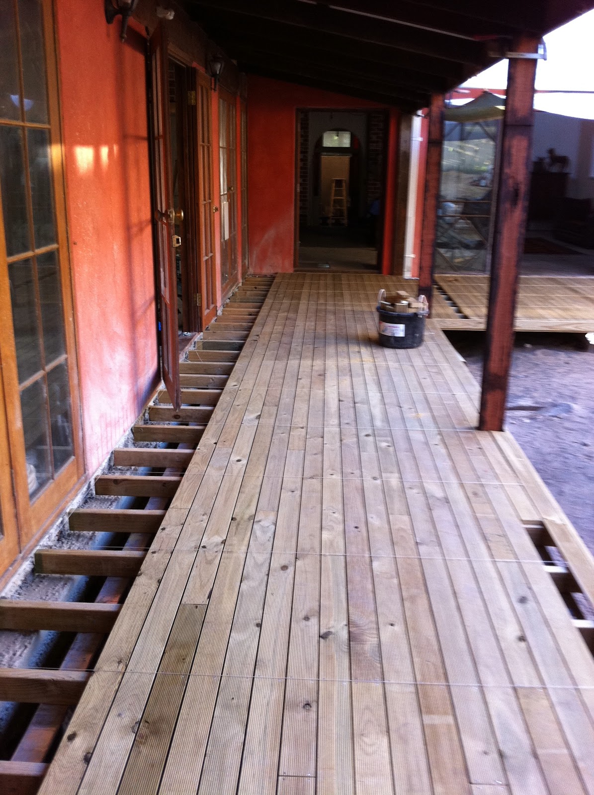
When I returned to commence the job, I found that the old concrete verandah had been removed, the soil level had been lowered, and Anna had used the drawing to pre-dig the holes for the metal stirrups which would be used in the place of timber stumps - to support the bearers. The timber was on site as with as most of the other materials that we would need. Everything was ready to go. Working backwards from the intended height of the decking surface, we determined the required level of the top of the bearers. We used my el-cheapo laser level to establish a reference line, and knew what height below that reference line the tops of the bearers had to be established. String lines helped to define the outer limits of the deck based on the required dimensions. The deck was to be in an L-shape, with the long leg being almost 10m ( 32.5 ft) by 2.1m (7 ft) wide. The short leg would be 7.5m long (24.5 ft) by 3.0m (10 ft) wide, meaning the 3.0m wide section extended a further 5.4m (17.5 ft) beyond the 2.1m section. This 10m long x 2.1m section was under an existing verandah. The edge of the deckline was to be directly below the verandah plate above it. This deck line was determined with the use of plumb lines from the top plate. The total area of decking would be about 37m2 (400 ft2).
Two views, one each of the legs of the "L shape" of the decking.

Laying out the bearers and stumps.
There are a number of ways to do this, but my preferred method is to make up the bearers full length, attach the metal stumps (stirrups), suspend the bearers levelled and in the correct positions, and pour the concrete around the stirrups. These days, it is common for bearers to be made up from two narrow sticks nailed and bolted together as a pair. In this way we made up the two bearers that were 10m long each, and the remaining 3 bearers which were 3m long each. The joints in the 10m bearers were staggered, mitred, and always over a stirrup. The bearers in this way were made from pairs of 120mm x 45mm CCA treated pine sticks.
The two 10m long bearers, propped up and in position, with concreting under way.   Temporary prop holding up the verandah until the new verandah posts go in.

The placement of frequent temporary supports, (made up of bricks, blocks, pieces of timber and fine-tuned with assorted packers) enabled the bearers with the stirrups already bolted on to be suspended over the holes ready for concreting. The laser level was used to ensure the bearers at each support and stirrup were leveled at the required height.  When the bearers were all set up ready, the concrete was mixed and poured around each of the 23 metal stirrups, and left for a couple of days to dry.
Detail showing the propped bearer with metal stirrup, suspended over the hole. The concrete would be poured half way up the 12 inch leg of the stirrup. Note also the staggered mitred joint in the bearer above the stirrup.  

Fixing the joists.
Before the joists were fixed to the bearers, the aluminium flashing was rolled out along the tops of the bearers. This flashing prevents the ingress of moisture between the pairs of timber making up the composite bearers, and thus greatly improves the durability of the bearers.
The joist positions were set out over the bearers, at 365mm centres. This is a little closer than the original plan, but putting an extra joist in the span will improve the decking by marginally reducing the spring in the decking. I am happy to be accused of over-engineering. String lines were used to ensure the joists were nailed in straight lines, and each joist was skew nailed from each side into the bearer below at each junction. Lots of 4 inch galvanised nails, pounded in by hand  using my trusty old Cheney hammer.
While the concrete was curing, I was still able to cut the joists to length ready for fixing down the next day. The flashing has yet to be rolled out along the tops of the bearers.
The joints in the joists were always staggered, mitred and centred over the bearers. The bearers and joists were always left "over-long", to be cut to final length later.
The long run of the decking structure, with most of the joists now cut to length, determined via stringline.
The original verandah posts had to be removed in order to undertake this work, before the bearers could be positioned in place. Amazingly enough, the old verandah top plate was full length - 10m (over 32 feet) which is a long 8"x2" of jarrah! You can't get them like that any more...  Anyway, in order to do this and provide the support, I first had to pick up the plate half way along it's length. The picture above shows how I did this. Once the temporary support was in place, the original posts were removed. The bearer/stump positions had been planned so that the new verandah posts would each be over a stump. 
Pam pleased to see the joists all fixed down. Some cutting to length still to be done.
The nailing down of the joists is the part of the job I always find very satisfying. You can really see the progress unfolding as you go.

Tips for fixing down the decking.
The decking boards on a completed deck are what is seen the most, not the structure below it. It is therefore very important that the boards are nailed down straight, with regularly placed fixings, and with nothing that jarrs the eye. Here are a few tricks to doing it right:

1. Work from string lines. With a stingline taut between one end of the joist to the other, the line of nails should be beautifully in line. It will look really good.
Nailing down in progress. Sticks in the foreground under the stringlines and ready to be used.

2. Place the nails in a consistent staggered pattern. Putting the nails in a straight line weakens the joist below by helping it to split open over time. By alternating the nails either side of centre (ie. either side of the stringline) When hammering in the nails, move the stringline as you finish each nailing, or you will leave a dent from the string in the soft pine!

String line used with consistent nail placement pattern. Note the remaining spacer - the others have been removed. Note also the tidy butt joint under the stringline.
3. Use deformed shank nails and skew them. Deformed shank nails have spiral shanks. This gives them greater holding power. You can see them rotating as you drive them in! Skewing the nails give them additional holding power to resist the forces exerted by the decking boards over years as they respond to the constantly changing moisture content of the boards between winter and summer. Decking nails in extremes of the Australian climate are notorious for working their way up and out.The use of deformed shank nails and skewing them greatly helps increase the life of the decking and reduce the maintenance.
Deformed shank (spiral) galvanised decking nails, skewed. Doubly good holding power. 
4. Maintain a consistent gap between the boards. This is very important, and is easily achieved using spacers. For this deck, I used 5mm spacers. These were made by docking up a piece of melamine faced MDF which was kicking around my workshop.  A nail is driven half way through each spacer, which is docked to about 60mm x 30mm. This enables the spacers to hang on their nails in between the boards while the boards are pushed up and nailed in place.  I made up a pile of spacers, more than 20, to make the laying process easier.
A few spacers shown in place here. Short board in foreground yet to be cut to length
5. Use reference lines. A nice tight string line, laid the full length of the deck in the direction of the decking boards, helps to ensure the first boards go in a straight line. While the use of spacers helps to ensure nice even spacing, pushing bowed and sprung boards up to them will not always guarantee that the spacing will be perfect. You will also find that not all boards are necessarily machined to exactly the same width. Different machining runs can result in slightly different sizing. Possible errors growing and multiplying are brought back in check by the use of additional occasional reference lines exactly parallel to the original reference line. Subtle corrections can be made to bring things back into perfect visual alignment. 
Looking good. New verandah posts in place. Full length reference lines used to ensure lines remain straight.
6. Cut good joints and stagger them. If you have to join decking boards end-for-end, make sure you place the joins over the joists, and keep the joins as far away from other joins as possible (ie. stagger them and spread them over the deck). Good looking joints are obtained by a small chamfer on the top face at the end of each of the two boards at a joint. This V-joint is much more tidy visually than two ends butted up with their arises intact.

7. Finish the edge cleanly with a fascia.
Having a defined edge by the use of a fascia board makes a huge difference to the look and the finish of the deck. Daggy ends of a deck are not a good look. Housing them within a nice clean border makes for a much better product.
Fascia board made with use of a decking board. In this case the brick paving will be built up flush to the top of the decking. That's the retaining wall partly under construction.  
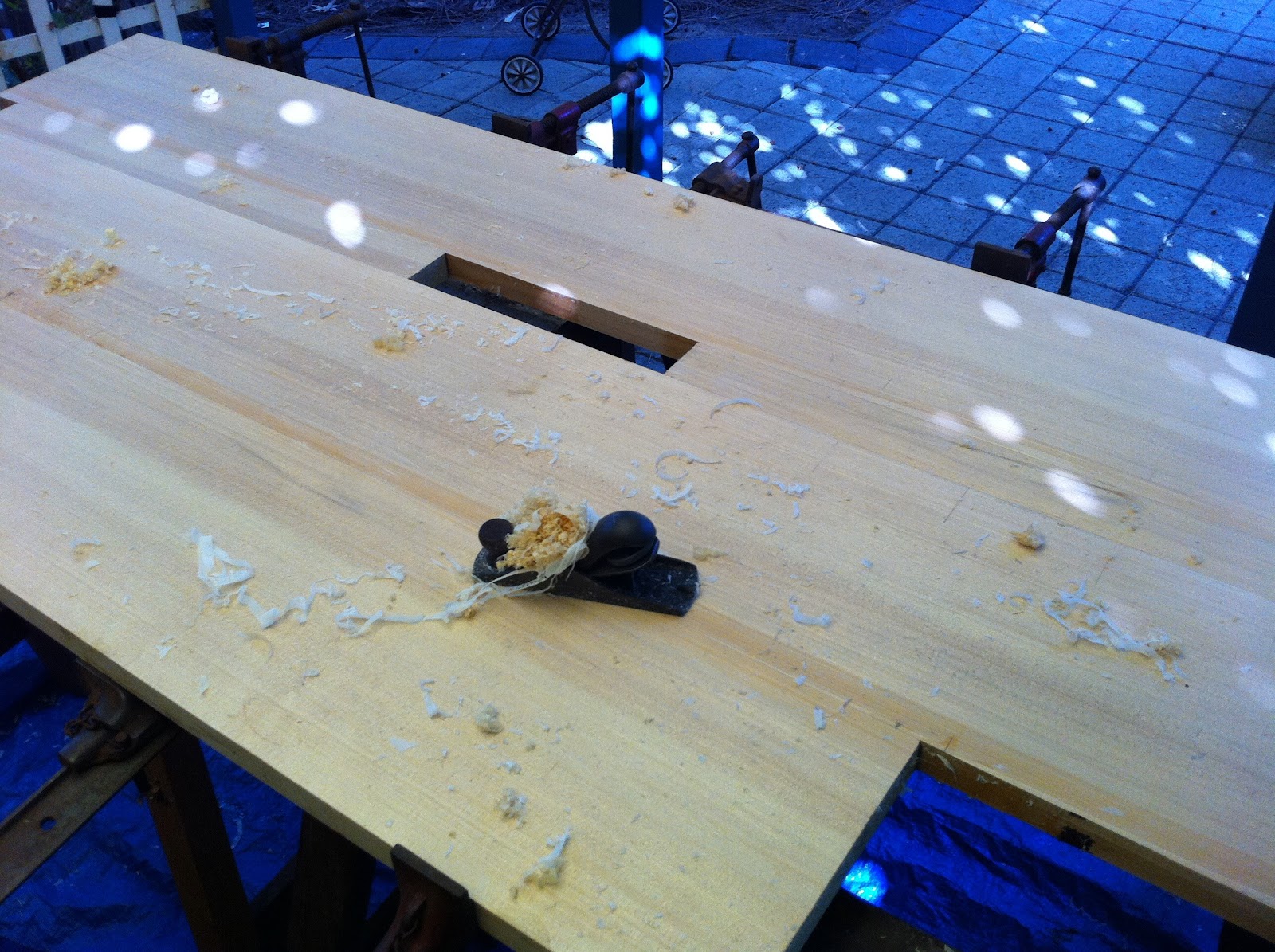
8. Use hand tools! Forget your drop saw and your nail gun. Seriously. For accuracy, speed and ease of operation, you just need a sharp tenon saw, a sharp block plane, a small try square and pencil, and a good quality hammer suitable for the task. When working under an array of nailing string lines, it does not make sense to walk each stick over to a drop saw, bring it back, and feed it under the stringlines again. While each board is laying on the joists, under the nailing stringlines, you can easily mark a square end over a joist, cut it to length beautifully square while laying on the joists with your tenon saw, and remove the arises on the ends with your black plane. Then insert the spacers and nail the stick down. I recommend pre-drilling the nail holes in the ends of the boards at the joins, to ensure the boards do not split at the ends. Skewed, of course.  Nail guns do not dress the joint like a hand driven nail will do. If you have a gap between the joist and the decking board, a nail gun will nail it down with the gap still there. A conventional hammer will close the gap as the nail is driven in, dressing it down. 

9. Take pride in what you do, and be your own harshest critic.
It's never OK to say settle for second best and say "that'll do". With power tools it's easy to make a mess of cuts. Too much power and not enough control makes for a lack of accuracy. However with hand tools it's all up to you how much attention to detail that you maintain and how accurate your cuts and hammering will be. That's one of the great things about using hand tools. 

Worried that your skills are not up to it? Keep your tools sharp and your hand skills will improve quickly while you use them on the job. Don't settle for second best. If your cut isn't square, do it again.

Nice job, eh? And it is really so easy to do...

So there you go... the story of a deck. Thanks again to my ever reliable off-sider on this job, Anna, for being so quick to learn and for putting up with my demanding attention to detail.
Now Pam, it's time for you to enjoy that sherry on your new deck...