Thursday, October 31, 2013

Woodcraft Week with Roy Underhill.

Yes, I have been in North Carolina doing a week of green woodworking with the legendary Roy Underhill of "The Woodwright's Shop" fame.
What a privilege it was for me to have been able to get a place in this course, in which I shared with nine other very nice blokes who came from all over the USA.
The-Woodwrights-Shop-Opening-Credits.jpg
For the benefit of those outside of the USA, Roy has been doing "The Woodwright's Shop" TV woodworking show for over 30 years. To date there have been 429 episodes made!  The inspirational starting point in their woodworking journey for many Americans, Roy's programs focus on traditional woodcraft & woodworking skills, techniques and history - using only hand tools and human-powered machines.

The setting for the course was Roy's beautiful property at McBane Mill, which to a wandering Australia has the most amazing array of tree species in the woods. For Australian eyes, it was fascinating to see the diversity of tree species in one small area of forest, as for us the diversity would be in the lower storey plants rather than the trees in any given area of forest. The small area of forest at McBane Mill held at least 18 different tree species - all of which would have had traditional uses due to their different properties.

The primary project for the week was that we would each make a shaving horse, using green wood. Along the way we would learn and experience a wide array of traditional woodworking skills and techniques.

There was a log jam in the riverbed, from which we extracted a nice walnut log, using cross-cut saws, axes and splitting wedges. This material was used to make the legs for our shaving horses, and other parts like the pins.
Roy inserts a sawyers's wedge as the walnut log is sawn with a crosscut saw.
Demonstrating the splitting of the heavier walnut log where it lay.
Trimming the riven walnut plank with an adze.
Using a froe to rive the walnut into leg-sized material.
The art of hewing to further shape the material for the legs.
Astride a bodger's shave horse, shaping walnut legs with a draw knife.
A view from the horse. Very nice walnut legs in the making!

We felled a Sweet Gum tree (a species of liquidamber), using axe and crosscut saws, to make all the "dumb heads" for our shaving horses. After hauling the log sections from the forest, we then used a variety of techniques and saws, hewing axes, adzes and draw knives to create our dumb heads.
Roy demonstrates the subtleties of swaging the rakers on a nice perforated lance-tooth crosscut saw.
The tree selected, the felling path of the Sweet Gum is planned. 
Sawing above and behind the scarf. Be quick and ready to move right away!
Sawing the log into suitable sections - two dumb heads in each piece.
The tree gave us enough to make 10 dumb heads. Now the hard work begins!
Making the dumb heads was the most laborious part of the whole project, but was a great way to learn to use a number of tools and techniques. Each one would be slightly different, depending on the maker and their journey with the tools.
Marking the lines on the log with a snap-line.
Dumbheads under production. lots of hewing to do.
Dumbhead taking shape. The long part is the leg/lever operated by your feet. The big block on top will be the upper jaw which holds down the work.
My dumbhead is going to have a smiley face grinning at the operator of the shaving horse.
The seat and body of the shaving horses we made from really nice 10"x2" Yellow Pine boards which had been obtained from a saw mill and were freshly sawn. This same material was used for the foot on most dumb heads. Riven oak and walnut pins were used to hold our horses together.
Using a beautiful boring machine from the 1880's to drill out my leg holes in the body of the horse.
Legs in, now shaping the body/seat of the horse.
Using a light duty shave horse to produce a heavy duty dumbhead.
"That thar's maa hoss". Under construction. Time to chop the mortises for the dumbhead!
Roy shows how to work out the mortise positions for the dumbhead.
My shaving horse is complete!! Works a treat as well.
When it comes to horses, you want to back a Grinner! Two embedded $2AUS coins for eyes. Meet Mr Smiley, from Australia.
As we learnt about the challenges and delights of working green wood, we were introduced to many wonderful old hand tools, including the boring machine, reamers, hand augers, and an assortment of saws, axes and chisels  ... just to name a few!
Roy demonstrates the Spring Pole Lathe.
We had a taste of Pit Sawing - quite literally.
I completed my shaving horse - which works very nicely too - but of course I cannot take it home. It's a bit sad, really! So I left if behind to be part of Roy's menagerie of gear at McBane Mill. ...Let's hear it for Mr Smiley!
What a wonderful ride this week!       Goodbye, Mr Smiley.

In addition to making our shaving horses, we did a discovery tour of the trees growing in the forest, and Roy gave us a taste of bowl carving, pit sawing, the spring pole lathe, and more. We also did a visit to Master Blacksmith/Whitesmith Peter Ross, to learn a little about the amazing work he does. He demonstrated the making of a Log Dog, just like we had been using when holding log sections while making our dumb heads.
Then there was the visit to "Ed's Lolly Shop" as I call it - The Antique Woodworking Tool store Ed Lebetkin operates upstairs above the Woodwright's School in Pittsboro, NC. A dangerous place to take your wallet!! So many fantastic tools for sale!  So many smiling people emerging with many beautiful tools in their hands...

With a lifetime of experience in this stuff, Roy just oozes with knowledge and information, which he generously imparts with gentle humour and enthusiasm.

Was it worth coming all those tens of thousands of miles, enduring all those painful hours squeezed into budget seats on numerous planes, to be part of Woodcraft Week with Roy?  ...YOU BETCHA!

Friday, October 18, 2013

Building a WA Blackbutt kitchen - Part 1. Getting started.

It all starts with an idea, a concept - and a need.
My customer had been pouring through magazines and the internet over many months, gathering up ideas for her new kitchen. She drew up a concept drawing, and we bounced around the ideas, construction implications, proportions, materials, and other practical matters.
The concept drawing of the kitchen.
I did a scale drawing on a piece of plywood, showing the detail of the proposed cabinets' face frames. This would help me determine the methodology for constructing it. All drawer fronts and doors will be set into the frame, with the frame creating "borders" around them. The cabinets would be made up of a group of Modules, each with fancy feet on the bottom front corners. The face frame "border" would be 40mm wide, with a bead and quirk along each side - like you would get from an old wooden moulding plane. However, with the grain of a lot of WA Blackbutt being pretty wild, I opted to use a router cutter rather than my trusty 3/8" Bead Moulding plane - to maximise consistency and minimise tear-out.
Experimentation. 4 pieces loosely held together to obtain my customer's approval.  
With approval and confirmation of the face frame design concept, and the methodology worked out, it was time to commence building the kitchen.  

A pile of vertical frame components and horizontals, machined up ready
For much of the year I have been working on the renovation of this lovely Art Deco house in Wembley, Western Australia. It would be nice now to face a whole new set of challenges.

Making the Corner Mitres on the face frames.
Accurate mitring of the corners after the profiles had been run was gong to be tricky, due to the double quirks/beads. I would use a pair of 3/8" dowels in each joint, glued and then screwed vertically in relation to the frames orientation.

My trusty dowling machine, which I fabricated from a 1/3 HP washing machine motor, a pair of hinges off an ancient old industrial fridge, and a Paulcall chucked workhead, has served me well for over 28 years. It has a nifty low-tech rise and fall mechanism made repeatable by the use of a set packers. The use of additional specially made jigs always makes functions consistently accurate.
This marking gauge was knocked up to reach over the edge of the mitre's short point. 
The borer in action, about to bore the second dowel hole. The slot through which the bit emerges from below the benchtop also normally has the dust extractor connected, to remove most of the waste. Works a treat.
That's the old beastie. She's bored a lot of dowel holes over the last 28 years. Removing the packer stack sees her retract below the docker bench. The dust extractor blast gate is below the bench under the slot. 
One of the face frames glued up. This one has the T joints as well, due to the centre mullion.
Cleaning up the completed face frames.
All those beads and quirks were going to be tricky top clean up. So a special scraper was made to assist the job.
Basic tools for cleaning up post glue-up. Plus the scraper.
A small scraper was ground from a blank into the correct radius curve and quirk size.
That's a Lee Valley beading tool blank that I've ground to profile.
The little scraper in action. No point putting into either of the Lee Valley beading tools, as you can't get into the inside mitred corners with them. This way you can.

Making the T-Joint on the face frames.
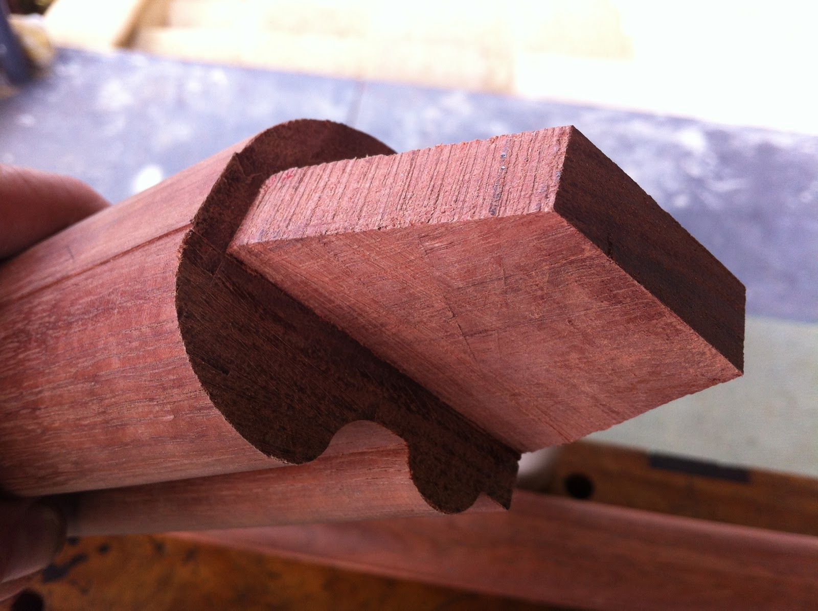
One of the face frames would have a mullion running vertically. Due to the beads, the joint would require a mitre through the bead on each side.
A rough attempt on the practice run. The system worked.
Accurate marking out is everything. The centre waste here removed with the radial arm saw.
Cutting is made easier with a 45 degree guide block, cramped accurately in the right position.
The saw plate is held flat against the guide block, and sawn down to the quirk base line.
Ditto on the other side.
Trusty No71 router plane consistently paring out the centre trench to depth. 
That'll do nicely...
Putting the cabinet sections together.
Often, I get so engrossed in what I am doing that I forget to take pictures. This part of the journey is a case in point.
Things are moving ahead well. Four of the sections in place on top of the toe rail.
All six sections in place. Now for the benchtops.
Next we would be making and fitting the benchtops. I had to get onto this and worry about most of the internal details of the cabinets later. We wanted to get the benchtops in and the plumbing and installations done for the dishwasher, sink, taps and gas cooktop all complete before I was to leave to go to the Woodworking in America conference in Cincinnati.

Yep, we made the deadline with about a week to spare... On my return we will continue the journey.
I am writing this post from my hotel in Cincinnati. the Conference starts tomorrow!

Monday, October 14, 2013

Gamble House. Iconic Greene and Greene architecture. Oh so nice!

Believe it or not, I am here in Pasadena, California, on my way to the Woodworking in America Conference in Cincinnati. Stopped in LA for a look around on the way there.
Gamble House, Pasadena
I found my way to Gamble House, one of the best known and best preserved houses designed by Greene and Greene in 1908, in the height of the Arst and Crafst movement.  It reminded me of the beautiful Rennie Macintosh stuff in Glasgow. I did the guided tour today. This stuff makes my heart sing!
Not a sharp corner to be found.
Greene and Greene designed everything right down to the light fittings. There are repeating design elements throughout the whole house, furniture and fittings. It was a partnership between the Greene brothers, the Hall brothers (cabinetmakers) and other highly skilled craftspeople in glass and stone.
The clients from Ohio, Mr & Mrs Gamble, of Proctor & Gamble, commissioned it and were able to afford it. While it only took 10 months to build, it cost $79,000 to make and fit out. In 1908, other houses in the area were being built for $1600. So the tour guide explained.
Lots of pegged through mortises in the joinery inside and out.
Sadly, taking photos inside the house was not allowed. There were 17 different types of timber used throughout the house. Each room would tend to have one or two types of timber used, but the same design elements were used throughout. Such incredible attention to detail.

If you've not had the pleasure of visiting this place, check it out on the web at www.gamblehouse.org .
Meanwhile, my USA woodworking adventure continues...


Friday, August 23, 2013

A Staircase Saga, Part 7: Making the Handrail.

With all the treads and risers complete, including the First Two Curving Treads, the next stage was to make and fit the handrail up the stairs. When there are winding treads, it is normal to have the handrail just going up the outside wall, where the treads are at their widest.

Creating the handrail profile.
In an earlier post I mentioned that my customer had found a handrail profile she liked on a US website. With some experimentation, I found I could get close starting with 60mm x 60mm material, and using my table saw to cut two rebates and then use three different router cutters to create the profile.
The picture from the US website, and my profile process.
One correction: Step 3 is actually a 22mm radius, not 19mm.
I need to start with sections of 60 x 60 material - jarrah. You can't just pop in to the hardware shop and buy this stuff!  The timber merchants don't carry this stuff anymore. It would have to be created. Almost the only way to find heavy sections of jarrah is through salvage. Specifically old bearers. These 4" x 3"
timbers sit across the stumps and support the floor joists.  While they were green when the house from which they came was built, they supported the floor (and the walls in a timber framed house) for that 50-100 years before the house was demolished. In that time the bearers have seasoned beautifully.

The sections of handrail I created started out as bearers - 4" x 3" timbers. The longest piece, at 3.6m (12 ') long, actually came out of the old part of my customer's house, where it had been for nearly 80 years. So nice to put it back into its renovated original home now as part of the handrail!

Step 1. Machine the 4" x 3" material into 60 x 60mm straight sticks, the required lengths.

Step 2. Cut the 25mm x 6mm rebates along each side of the base of the sticks, on the table saw.

Step 3. Create the bottom beads by running the router cutter in the rebates.
The router runs along the rebate, from below, to create the lower bead.
Step 4. Create the top big round-overs with a 22mm radius rounding-over router bit.

Creating the top round-over with the big 22mm radius bit.
Step 5. Create the small round-overs under the top, using a 6mm radius rounding-over router bit.
This one's tricky, a long reach. Rounding over the underside of the "breadloaf top". 
That's it! Profile created. Note: The secret is to have three different routers will the cutters set up in them, undisturbed until all handrails and balustrading is completed!
Not a clear pic... but you get the idea. Notice the two tiny  quirks on top?
Planning for the joints.
The normal height for a handrail is the same as that of balustrading. Under the Building Code of Australia, baustrading must be a minimum of 1000mm high. With balustrading on a flight, the top must be a minimum of 865mm when measured at the point directly above the nose of the tread below. While this does not really apply here, it was a good starting point to draw this line 865mm above and parallel to the nose line below - which is about at an angle of 34 degrees. Of course, where there are winders this idea all turns to mud as the angles change from nose to nose around the corners. So then we experimented, to find the best angles around the corners, and the best transition points for where these might meet the ones on the straight flights. After many lines were drawn on the wall, we then decided on the best line to follow.
Hand rail pillars fitted to the back wall on the agreed line. 
The hand rail pillar positions were worked out, and then fixed to the wall. The joint angles and positions were now determined.

One joint, drawn on the wall. Now for the bridle joints...

Cutting the joints and putting the rail sections together.
The interesting thing about these bridle joints is that they were different, depending on whether the tenon would protrude from the top of the adjoining piece or disappear into the adjoining piece.
Cutting the tenon on a bridle joint.
Remember the two tiny quirks along the top of the handrail? These were there to aid the accurate marking out and cutting of the joints, and were used to aid the accurate sawing of the joints. It worked a treat...  otherwise it would have been very difficult to have done the accurate marking out for the joints.
Nice tenon! ...For where the tenon disappears into the adjoining piece.
Nice open mortise! ...for where the tenon will protrude from the adjoining piece.
The three pieces from the back wall, with joints cut ready to glue up.
So how do you do accurate cutting of joints like this on site? It was made so easy by using my trusty "Saw Horse on Steroids", which was so useful for building the winders on site.  You can't do this kind of stuff easily or accurately with power tools. It's hand tool territory! The holding power and options of this bench are wonderful for this work.
Joints pulled up, rail in position on the back wall, and glue drying. Looking good! 
The top joint on the back wall. Protruding tenon has been cleaned off.
Glue dry, so time to clean it up.
Those tiny quirks are now removed with a curved scraper and then hand sanded smooth .
The curved scraper does a great job. Made from a recycled saw blade.
The long run being cleaned up. It's over 14 feet long!
The long run cleaned up and in place.
There was much deliberation about the two corners. With the rails meeting at complex angles, it was not going to be possible to have a clean joint on the corners. Hence the gap between.
Where the long run meets the back wall. A 25mm gap to remove any finger trap.
Where the back wall rail meets the lower section. Another 25mm gap.
Other than the polishing of the handrails, there is one handrail task left (other than the balustrading upstairs). See that bottom end in the pic above? I have still to make the finish... the handrail is to curve and and down, mirroring the curve of Tread #2 below it and dropping the equivalent of one rise. A spiral finish. Eehah! that one will be a challenge! That will happen sometime in the future.

After the handrails were completed, the trim along the walls around the winders were added. The staircase is getting closer to being finished.

To complete the staircase, the remaining tasks need to be done: the spiral finish at the bottom of the hand railing; the balustrading on the top floor; the making of the door into the "hidey hole" underneath the lower sections; and the polishing of the entire staircase.

What a great project. A pleasure and a privilege to make, too.

Thursday, August 15, 2013

Recycling old saws into scrapers.

Sometimes, an old saw is just not worth salvaging.
Sure, if good enough, the handle and bolts/nuts can be all be saved to use again when repairing or re-building another saw. There are times when it is the saw plate that will be utilized instead.

Amongst my huge pile of old saws awaiting rebirth, there was a very tired post WWII  Disston panel saw which had a ruined handle. The saw plate had a bit of surface rust, but nothing too drastic. I had a need to make some more curved scrapers for spoon carving, so set about cutting up the saw. This was initially done with a guillotine.
Saw meets guillotine ... 
Dividers were used to draw curves on the ends of the pieces of saw plate, and the guillotine and  heavy tin snips were used to remove much of the waste. The rest was done with a bench grinder, to create the final shapes of the scrapers.
The first few scrapers taking shape.
Once the required shapes are made good with a bench grinder, the scrapers's edges need to be prepared with a nice fine file. We are looking for a very clean edge , square to the faces. A burnisher is then used to create the burrs which make a cabinet scraper work like a fine plane - taking very thin shavings. Wonderful!

Custom shapes for scrapers.
While I had been making up a batch of convex curved scrapers for spoon making, another task came along yesterday. I am making handrails for a staircase at the moment, and I needed a concave scraper to help clean up the top curve of the handrails.

So I grabbed one of the incompleted spoon scrapers made from the saw above, and re-shaped one side with a concaved radius suitable for my requirements on this job.

The scraper will remove the lines left by the router cutters from the handrail top.

The concave side of the scraper and the type of shavings it created on the handrail. Nice. 
So simple and so effective. Scrapers are fantastic tools which are easily made my recycling old saw blades - so long as they are not too pitted from rust.

I usually make spoon scrapers with a different radius curve on each end. However with the one above, I chose to leave the saw teeth in place... as a reminder of where it had come from, it's former life.
It's a nod to that nice old Disston panel saw. It lives on!