Sunday, August 11, 2013

A Staircase Saga, Part 6: The First Two Curving Treads.

All this year I have have been privileged to be working on a big renovation, where I have been doing a wide range of carpentry and joinery work. An Art Deco home built in the 1930's, the house has been expanded upwards and outwards. The addition of a second storey brought about the need for a staircase. Another job for me, which I relish. Stairs are a wonderful brain challenge and have always been a great chance to push and test my skills.

Where possible, the old original jarrah roof timbers removed to make room for the top storey are being recycled back into the house by way of the staircase, window sashes, and many other uses. Most of the straight treads in the stair case are made from glued up rafters from the original roof.
Yep, it ticks all the right boxes...

Previous posts tell the story of the Staircase Saga thus far:
Part 1: Building a Staircase with Winders.
Part 2: Getting Started.
Part 3: The Big Flight.
Part 4: The Short Flight.
Part 5:  The Winders.

It seems that somehow I don't have a pic of the staircase with the winders completed which shows the missing first two treads.
Winders completed... now for the first two treads.
In the pic above, the lowest tread in the foreground,  is tread number 3. Completing the winders meant that treads 3 to 20 are done. There is still the handrail to do and a few bits of trim around the wall edge of the winding treads - however the priority now was to make the first two treads.

The original architect's plan, showing the first two treads poking straight into the entry hall.

In the original plan, these first two treads were going to stick straight into the entry hall. Discussing this one day, we hit on the idea of making these treads flow out into the room by both curving around to meet the walls on either side. It seemed like a really good idea! Another fantastic challenge for me, and I was looking forward to bringing the concept to reality.

Planning the curving treads.
If you have been following this saga, you won't be surprised to find I start out with a set-out board with a full scale drawing.  It was important first to transfer the positions of the newel posts, walls and other key features onto this board. In this house which is 80 years old, not many of the original walls and floors are square or plumb. I needed to record all this on the set-out board, as everything would need to be scribed to fit the existing floors, walls, and staircase structure.
Part of the full scale drawing board, showing the right hand end.
Never mind the walls and floors, the staircase was all being built to be square and plumb to the planet! So allowances for scribing and fitting would need to be made to all components. All of the winders in the first set were radiating from the same theoretical point in the newel post. The curves would also be drawn from the same theoretical point and from a similar position on the other end. The use of these points and careful marking out would enable the creation of a set of very accurate templates for various components for the two treads.

Formers, riser boards, and nosings.
I needed to decide upon the method to be used to make the curved riser boards. Years ago, I used the multi-kerf method to bend jarrah sides for a couple of coffins I built. I reckon that would be the way to do this. So I did some testing.
A rough test, but it was going to be a winner.
Using my trusty radial arm saw, a series of saw cuts were made across the stick (165mm (5 1/2") wide, leaving approx 2mm of material uncut. These kerfs were cut where ever the curve would be formed, plus about an inch either side. This way one continuous stick (19mm thick) would be wrapped around the face of each former to create the riser boards.
Cutting the kerfs with the radial arm saw.

The formers were made using 16mm (5/8") plywood and bits of jarrah.
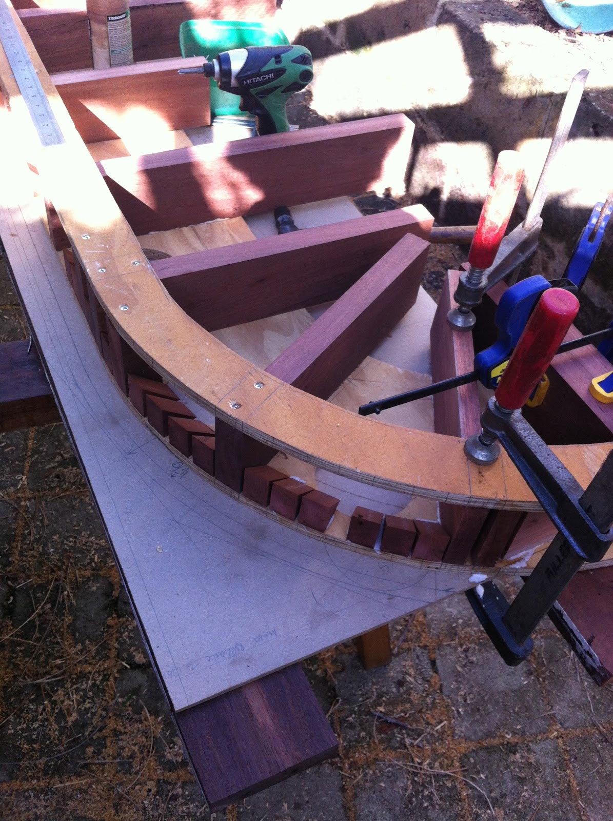
Making up the former for Tread 1's riser board.
Lining blocks were glued top and bottom between the radial ribs - just like the inside of an acoustic guitar.

Former  with lining blocks ready to have the riser board attached.

You can never have too many cramps! Gluing the riser board to the former.
The riser board has a rebate running around the top edge, like a continuous barefaced tenon running full length around the top. This would be housed in a groove running full length of the nosing 15mm behind the front edge of the nosing.
Gluing a couple of layers of thick jarrah veneers to the back of the bottom edge of the riser board. 
The former for Tread 1 was made 20mm short of the width of the riser board, to allow for scribing of the riser. There was a 12mm (1/2") fall in the floor from one end to the other.  This 20mm protrusion was strengthened by gluing a couple of 2mm thick veneers around the curved sections.

The nosing for Tread 1 being glued up in its segments.
Each segment joint in the nosing had 6 dowels and a biscuit held with epoxy resin! Cramping it up was tricky, but worked well.

Accurate templates and the router with a long flush-cut bearinged bit would cut the sweeping curves in the nosing.
The rebate cut on the inside would hold the tread insert behind the nosing.

The groove cut on the underside of the nosing, to house the riser board. 

 
The two tread units completed and placed in their stack - except for the inserts. 
Tread inserts cut to fit. Time to do the installation!
The tread units were now complete, and ready for installation. This was going to be a tricky job, as everything would be to be scribed to size and position and fitted.

Installing the two tread units.
First I had to sand the floor in the immediate area to get the floor area ready.
Then I had to scribe the bottom unit (Tread 1) to the floor and walls.

Cutting the horns to length to achieve a snug fit to the walls.
Scribing the riser board to follow the contour of the floor.
The bottom unit was leveled using packers, and scribed to the floor contour using the old trick of a block of wood and a pencil at the lowest common denominator. It is as accurate as the cutting to the line, which was the next stage. It worked a treat, using my rusty hand saw and jack plane. With much checking of the measurements and position, Tread unit No 1 was screwed to the floor. Unit 2 was then made to fit the walls, and fixed to both Unit 1 and the wooden staircase structure in the correct position.

The inserts being fitted to the treads. These were nailed into place.
The final fixing job required me to climb in through a small hole in order to screw the top riser board to tread insert 2,  from behind. It was a squeeze but a great moment. This complex and demanding task was completed!
It's no wonder I'm smiling!! ...All treads now completed.

Righto. Now it's time to contemplate the handrail and wall trim...
I guess I'd better make the door for the hidie-hole too!

Saturday, August 10, 2013

Saw sharpening... a balance between rake, fleam, and set.

At the Perth Wood Show last weekend, I picked up a lovely Canadian-made Disston tenon saw from the second hand tool stand run by the Hand Tool Preservation Society of Western Australia. It's a beauty! However it just needed sharpening...
Yep, a very nice Disston tenon saw, with the handle in very good condition.
I have a few odd Disstons made in Canada. This is a new addition to my Canadian bunch. 

With a three day gig this week at a primary school doing woodwork with the K - 2 students, I needed another sharp saw on hand. I also had another tenon saw needing sharpening for the event -an older Disston saw. So it seemed a golden opportunity to get them both done during a window of opportunity I had on the day before the school program commenced.

The older Disston tenon saw, made in Philadelphia USA.
About the variables in saw filing - rake, fleam, and set.
In a nutshell, RAKE is the vertical angle of the face of the tooth, which also determines the aggressiveness of the cut. If the rake was 0 degrees, the face of each tooth would be straight up and down. FLEAM is the angle of the face of the tooth in relation to the line of the teeth. If the fleam was 0 degrees, the teeth would be filed straight across. Rip saws are commonly filed like this, so that the teeth work like little chisels. Crosscut saws are filed with fleam up to as much as 30 degrees, which makes the teeth like little knives as they slice through the fibres of the wood. Set is the applied by bending alternating teeth either side of the tooth line. Increasing the set widens the kerf cut by the saw, which stops the sawplate from binding in the wood. However, the wider the set the harder it is to push the saw, and the less accurate the cut. Dovetail saws typically have minimal set, which enables greater accuracy.  

These saws are going to be used mostly by small kids. I am still experimenting with filing angles and the amount of set which works best for the little people (age 4 up) who have short arms, limited muscle, and who are often using saws for the first time in their lives. This means that they are yet to get the hang of moving their saws in a dead straight line. The wobbling wrist and arm will tend to make the saw plate bind in the kerf, so a bit more set in the teeth than usual will help to prevent this. The trade off is that they have to remove more material to have a wider kerf, meaning more energy is required. It's a balancing act, and my experimentation is yet to achieve the optimum saw configuration for the little kids. The other ingredient in the equation is the type of material being cut. With the kids, I almost exclusively use softwoods and plywoods. With softwoods you would normally use a greater fleam angle than you would for hardwoods. So, I continue to experiment...

The new saw in the saw vise, ready for sharpening.
After jointing, shaping and setting the teeth, I filed the teeth with a rake of 30 degrees and a fleam of 20 degrees - hence the angles. The kids will be mostly crosscutting in softwoods.

Teeth being filed for cross-cutting, with a rake of  30 degrees and a fleam of 20 degrees. 

Two nice Disston saws, sharpened and ready for action.
I would have between 4 and 6 tenon saws in operation at the school. The picture below shows my standard "sawing station" set up. This 4 saw station is a bit like having 4 bench hooks set up on a pair of sawhorses. It also works really well, for right and left handed students.

The sawing station set up at the school ready for use. 
As I finish this post, I have completed the 3 day gig at the school. Eight classes of students had a great time  making stuff - using hammers, nails, saws, and a  pile of wood pieces. The saws worked flat out for much of that time. Amid all those cutting their pieces of wood to size, there are always a few kids who just love sawing! They might not make much, but they do create piles of little pieces! It's great seeing kids enjoying using tools for the first time. So empowering.


The verdict? For the really little kids, the 4 and 5 year olds, I reckon we might need just a little more set in the teeth...    I'm still looking for the right balance...

Monday, July 29, 2013

A Staircase Saga, Part 5: The Winders.

With the Big Flight and the Short Flight in place, it was time to make and fit the two sets of Winding treads which take the staircase around the two corners.
The positions of the lower winders, as marked on the full scale drawing.
The positions of the upper winders, as marked on the full scale drawing.
Chopping the housings for the treads and riser boards on the appropriate angles and positions was a tricky job, which I had done before assembling the posts in the Short Flight.
The nosings and riser board behind were fitted, then the next pair below.
Nosings with floorboards behind were to be used rather than full solid treads, as the widest tread would be 550mm (22") at the widest point - much too wide due to potential movement. So nosings were made with a rebate at the back to take the floorboards to be used to complete the triangular treads. This would be a more stable construction methodology.
Using my trusty No. 5 1/2 jack plane to clean up and fit the angled rear faces of the nosings where they meet the riser boards behind. 
The support structure goes in for the lower winders. I did a lot of time under there! Ow, my back!
The angled props taking shape under the lower winders.
The lower winders emerging from the lower newel post. Lookin' good!
The top Winders being fitted. They'll link the Big Flight to the Short Flight.
The bottom winders, with floorboards behind the nosings fitted and fixed.
It was great to get the two sets of Winders installed. They still need the trim fitted around the wall... and the handrail... and Treads 1 & 2.
At last, the staircase is usable - even though Treads 1&2 are yet to be made. That's the next challenge!

While a lot of work, I find building staircases is very satisfying indeed...

OK, time to contemplate the bottom two treads...


Friday, July 26, 2013

A Staircase Saga, Part 4. The Short Flight.

Some months after the Big Flight was installed, the time had come for the Short Flight to be added. Much had happened in that period, including the installation of the underfloor heating, the laying of the jarrah floor over the top, the building and defining of the new wall and the opening in the upper floor, the plastering and gyprocking of walls and ceilings, and more. With the plastering of the walls completed and now dry enough, I was looking forward to working on the stairs again.

This staircase will have two sets of winding treads, separated by a pair of normal straight treads - which I shall refer to here as the Short Flight.  Above the second set of winders will be the Big Flight. Below the first set of winders will be a couple of straight treads which will give a sense of "spilling out" into the hallway, wrapping around to meet the wall on either side of the staircase. Of course, then there's the handrail and the ballustrading upstairs! There's a way to go yet before this staircase saga is completed...

Back to the drawing board.
What a surprise! The actual measurements were checked against the original drawing, including the position of the tenon on the bottom of the Big Flight's inner stringer. This tenon would be fitted into the newel post which would be fitted around the wall in the opening of the wall.
The original full scale drawing.
Essential to the short flight is the three newel posts which are part of this component of the staircase. The drawing above shows the relationship between these posts, the wall through which the stairs pass, the two sets of winders, the big flight, and of course the short flight of two straight treads.

Making the newel posts.
The only way to get 90 x 90 mm jarrah is to recycle old verandah posts, obtained from Salvage yards.
Buried under layers of old paint, it is a lucky dip until the material is machined up.
Amazing how many nails and screws are lurking under the layers of paint on the verandah posts.
Two of the three newel posts required for this section will have a 30x30mm rebate out of them to fit around the wall snugly, through which the staircase will pass.
One part of the full scale drawing of the three newel posts and how they relate to the short stringer and the wall.
The Handrail.
A short section of handrail/balustrading will extend between the two lower newel posts. My customer found a profile she liked on a US website, so I did some experimentation to see if I could get close. I found I could get close starting with 60x60mm material, the table saw, and three different router cutters! This profile will be used for all of the handrails to be added later. I made the short section I would need for this short flight section.
The handrail profile... and how to make something close!
The balustrade panel.
Between the hand rail, the stringer and the posts either side, would be some balustrading. While discussing  the design possibilities, we hit on the idea of matching the original entry hallway woodwork adjacent to the staircase. Brilliant! I grabbed a piece of drawing paper and a ladder, and did a tracing of the original tulip panel.
The original decorative woodwork above the hallway.

Tracing the tulip panel
The tulip design was cut out and then used to draw around on the jarrah panel.
I don't use my scroll saw often, but it's great for jobs like this.
The panel was made! What a good idea. Time to put it all together.

Putting it all together.
Using the full scale drawing, all the components were cut to size and angle, the mortises chopped, the tenons cut, and every joint test fitted. Time consuming, but essential before doing a dry run cramping it all together. If it is all sweet, it will be disassembled and then glued up in situ.
All these angles are very tricky to cut and fit. I'd be lost without the full scale drawing to take measurements off.
These two posts straddle the wall. The narrow panel will hide the wall end between the posts. 
Looking good for the test fit.
With all the components and joints fitted, it was time to bite the bullet. Glue-up time, on situ.

The glue-up begins, That's the hole in the wall we are going through.
The short flight starting to take shape.
The short flight develops further.
Another view. That's the big flight up around the corner.
Another look. Yep, the tulip panel was a nice idea!
Gluing all this up was a huge job. The upper post had the big flight's tenon housed into it as well as the nose of Tread#11. It had to be fitted around the wall, and the treads and  a couple of risers put in place - as well as the balustrading/handrail, etc. All in all, I was very pleased the way it all came together.

The short flight was now in place. The next step would be to build the two sets of winding treads, which go either side of the short flight.

Sunday, July 7, 2013

A Staircase Saga, Part 3. The big flight.

The staircase I am building completes it's ascent with a big straight flight, with Tread Nos 11 - 20. The whole staircase will be a very functional and beautiful feature in an 1930's Art Deco home which is being renovated. Lucky me ...  I am blessed with the task of providing a significant amount of the carpentry, joinery, and cabinetwork within the building. It's such a privilege!

The planning process is outlined in an earlier post: A Staircase Saga, Part 2. Getting Started. Having done the planning, then bought and dimensioned the stringers, it was time to get stuck into building the big flight. This would be the first part of the staircase build, as it would determine the position of the opening on the top floor. It would need to be in place before the plasterers and gyprockers could do their thing and would become part of the structure of the building once everything had been built around it. It would be in place for some months before the rest of the staircase could be completed.  It was also going to be very heavy!

I started setting out the treads and riser-board positions on the stringers. With these drawn in place, I then made up a couple of jigs for the router to enable accurate housings to be consistently cut.
The tread housings were cut by the router using a purpose made jig.
The pair of stringers with tread housings completed.
A different purpose made jig was used for cutting the riser board  housings.
With all the housings cut, it was time to fit the treads and riser boards. 
Making the treads. The intention was always to recycle the old jarrah rafters from the original roof into the treads. The rafters were docked oversize, scrubbed with a wire brush, scanned with a metal detector and de-nailed as required. I then machined the material, flattened and dimensioned the sticks to 47mm thick and as wide as possible for each individual stick. Suitable wider boards from the roof timbers would be machined to create the riser boards, finishing at 18mm thick.
Rafter sections (right) cleaned up ready to be machined, and potential riser boards (left). 
Three treads simultaneously glued and cramped.
A 1/4" plywood spline, 25mm (1") wide, was inserted full length in each join in the treads, and epoxy glue was used for the joints. It worked out mostly at 3 rafter pieces per tread. When the glue was dry, these treads were machined to the required 45mm thickness.A finished tread depth (width) of 282mm was required for each tread. The riser board face sits 16mm (5/8") behind the  nosing of the tread, so I machined the required groove on the underside of the treads, ready to take the tongue (a barefaced tenon) on the top of the riser boards. The noses of  the treads were rounded over with a 1/4" radius rounding-over router bit.
With the treads, risers and stringers prepared, it was time to put it all together. Well, it was going to be too heavy to put together in my workshop and deliver to the site - so it was going to have to be assembled on site. Each of the joints was individually test fitted at my workshop, then all the components taken to the building site ready for assembly.
The test fitting of the treads and risers in full swing.
View of some tread ends, showing construction with plywood tongues in the joints.
Lookin' good... from the back of the stairs.
The big flight was glued and assembled on site, on a pair of sawhorses right below the opening in the floor above, and then two chain blocks I had rigged were used to lift the big beastie into place.
Much careful planning by way of a scale drawing of the wall.and floor joist structure at the top end, and the preparation of the top of the stringers had been undertaken during the construction of the stringers, which enabled the stringers to be parked on the top of the wall plate when the top flight was lifted into position. While getting it all up there was a challenge, it finally went beautifully into place. It was a winner! Props were placed and secured, to hold the lower end in position, and several fixings put into the wall through the underside of the stringer against the wall. A couple of bolts through the top of the stringers into the floor joists, and the big flight was in place.

The next step was to build the wall on the kitchen side of the big flight, joining the outer stringer to the floor joists and ceiling above. Below this stringer and the big flight will in be the mini-laundry behind doors. The big Blackbutt posts framing the laundry area would also serve as the props for the outer stringer.
The upper wall frame being built around the top flight.
The big flight was in place. Nothing else would happen on the stairs for a few months, until the other trades had completed all their work around the big flight and the openings top and bottom and through the wall.

Great to see once again how careful planning and preparation has once again paid off.
While I had plenty of other tasks to get on with around the building site, I would be looking forward to getting back onto the stairs again downs the track...