Friday, May 29, 2015

Combining a Shaving Horse and Bowl Carving Bench - My "Mk III" Shaving Horse.

I've got about 8 shaving horses, which I use for running public workshops. I had previously made a batch of shaving horses from packing crate material and other recycled wood, which I did a post about  in July 2014.
Since then I have made another version, like a super-modified saw horse. Let's call it the Mk II - a multifunctional shaving horse and bowl carving horse combo. My favourite horse, it is about 7 feet long, has fixed legs, and a heavy vise built into the tail of the bench. All this limits its portability.
Some of the original shaving horses, English Bodger style on the left and Dumbhead style on the right.

The Mk II Shaving Horse / Carving bench combo. A beautiful beast - with a tail vise!
The Mk II has fixed legs, as it is a supermodified saw horse at it's core. Being all jarrah, it is heavy. It is very versatile in its holding capacity, but there are times when it is too big or tricky to transport. 

I was invited by Timbecon to demonstrate Green Woodworking at the Brisbane "Timber & Working with Wood" Show on 15-17 May 2015. With my gear needing to be transported three thousand kilometres across the continent, I had the need to make a portable and versatile bench fairly quickly to catch the truck. Hence the Mk III was conceived. I was going to Brisbane, as the Mk II was not going to be friendly to ship on a pallet of stuff.

OK, so lets make a shaving horse combo which will be easier to ship. This means its got to have folding or removable legs...

Deciding on the Characteristics of the Mk III.Shaving Horse.
I built my first shaving horse, Mr Smiley, at the legendary Roy Underhill's Woodwright's School in North Carolina in late 2013. This was a classic "dumb-head" style, made entirely by hand from timber we mostly extracted from the forest using cross-cut saw and axe, then fashioned with side axe, adze, shaving horse, draw knife, brace and bit, etc. Amid the stable of horses at Roy's, there were a couple of shaving horses of the English Bodger's style. I particularly liked this style.
Me using Mr Smiley. I left him in Roy Underhill's Woodwright's School stable. 
Mr Smiley, with embedded Australian $2 coins for eyes. 

Horse-cam. Making Mr Smiley's walnut legs on an English Bodger's style shaving horse at Roy's.
Not sure why, but I seem to prefer the English Bodger's style of Shaving Horse. Hence the Mk II and Mk III were both made in this style.

Veritas Tools used to have free Shaving Horse plans available on their website, which I saw before planning the Mk II. One of the things which caught my eye was the use of the back end of the bench/seat for additional holding options. Now there was an idea...


When doing bowl carving, I have been using a very low wide-topped saw horse which has dog holes in its top for gripping he bowl blanks. What if these functions were built into the back end of a shaving horse? When I made the Mk II, I even installed a big vise in the back end of the bench. Awesome.

As the Mk III was to be portable, I would make the horse a little shorter than the MkII, put a twin row of dog holes in the bench for bowl carving, and not install the vise (which would add a lot to the weight).

Of course, it would be made from recycled wood. I happened to have a couple of ancient house beams, of Oregon (known outside Australia as Douglas Fir). I docked one of these to length, dressed the stick, and bored dog holes in it. It would be a nice solid bench/seat. Jarrah would be used for the legs, treadle frame, the ramp, and the bench accessories. The legs would fold, and be held flat to the bench when packed flat, using a couple of coach screws. To put up the legs, undo the coach screws, fold the legs out, and wind in the same coach screws in at the base of the struts. Solid as a rock.

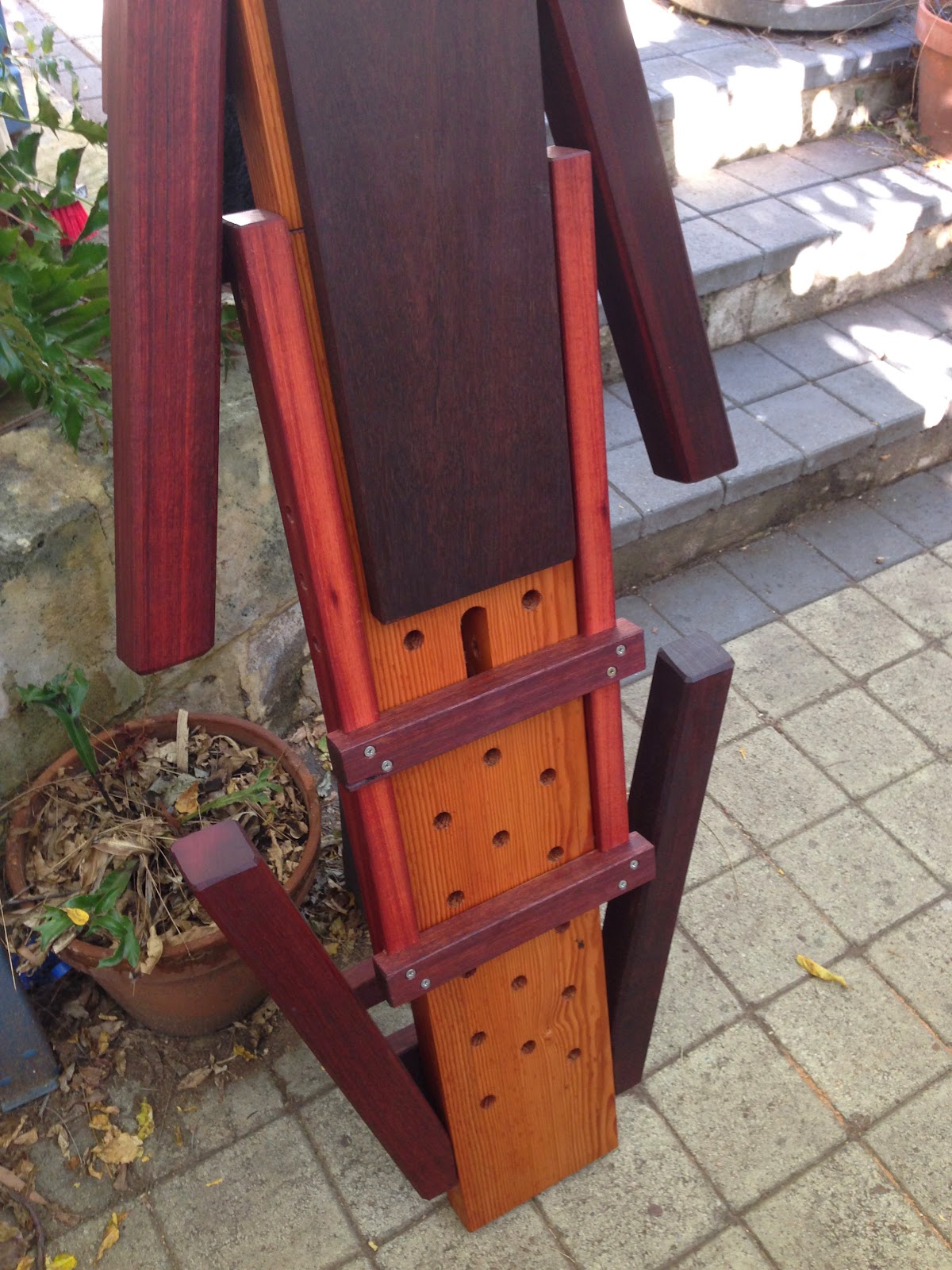
The horse/bench folded flat, with all the accessories.

Fold up the legs, and wind in the coach screw at the base of the prop.
The assembled shaving horse. A rotating head on the treadle frame.
Variability with 3 hole positions in the bench, and 3 holes in the treadle frame.
Rotating head, and a sliding support block under the ramp.
Bowl holding on edge. The foot vise is fantastic. You sit behind the end post.
A couple of sets of folding wedges and side blocks.
Great gripping power when adzing out bowls.
Holdfasts go well for holding work too.
Not a bad beast. Solid, reliable, and versatile.
It's also much easier to ship and to pack away than the Mk II.
You still need a small box to hold the bolts, head, and accessories.
The Mk III takes about 5 minutes to assemble, creating a very solid saving horse, bowl carving bench, and general low bench. ... I do miss that tail vise though!

I love the way ideas evolve...
The Mk III was test driven for the first time at the Brisbane Wood Show. A nice horse too.
The film crew from QUT did a story around my demo area.
Here you can see the Mk III in action, ridden by Bernie the Journo.
This pic gives an idea of the size of the horse.

Don't worry, I am already thinking about the possible characteristics of the Mk IV!!
The buzz-"phrase is "Continuous Improvement", isn't it?


Note:  GOOD NEWS!
It is exciting that so many people are interested in Green Woodworking.

As a consequence I have been contacted by an overwhelming number of people seeking more info and measurements for the Mk III Combined Shaving and Bowl Carving Bench.
You will be pleased to learn that I will have detailed plans for sale in the near future, soon after the upcoming launch of my website. Yes! A proper website after all these years! This should be on line before Christmas 2017. There will be other plans available too, and other resources, as I am always cooking up new devices, like my new Tilting Bowl Carving Bench. 

Here are a few pics of the prototype. A couple of tweaks and small changes, and this awesome device will also be up on the new website with plans available for sale.  


The bowl blank is held between the two end stops by a pair of folding wedges.

The Tilting Bowl Carving Bench has 4 angle positions in which your bowl blank can be held.
Flat (0 degrees), 30 degrees, 45 degrees and 60 degrees. 

Work raised in the 60 degree position. It also can be held at 45, 30, and 0 degrees (flat, as per the previous pic)


In the flat position it is also good for paring with your gouges after the adze work.


Remember, Folks, plans for the MkIII Shaving Horse (a combined Shaving Horse and Bowl Carving Bench) and the Tilting Bowl Carving Bench will both be be available soon just after the launch of our new web site - along with other plans, plus lots of free information and inspiration to help you on your green woodworking journey.

I just love to share the joy of traditional woodworking with others.
Wood is a gift from the trees. Honour the trees by making beautiful things from them.

Greg Miller, Perth, Western Australia.  31 October 2017.   

Note: the plans are now available to purchase. They are quite comprehensive, being 9 A3 pages made up of scale drawings and some photos, but you can always print them out in A4 if you wish. Available in pdf format, the cost is AUD$50, which in the current exchange rate is approx US$37. To all those who have been waiting, my sincere apologies. I had hoped the plans would be available on my hew website, but this is not yet operational.

To purchase these plans, go to our Etsy Shop!
Kind regards,
Greg.


Love that Double Spring Pole Lathe!

It all started when I did the Woodcraft Week with Roy Underhill in North Carolina in November 2013. I saw and tried Roy's Double Spring Pole Lathe.

Roy Underhill at work on his Spring Pole Lathe.
Roy's lathe knocks down and all fits into a golf bag! It was the first time I had seen a pole lathe in action, and I knew I would have to make one when I returned to Australia. Of course I had seen many pics of the English style with the massive long poles, but this version, which Roy says he found in a 17th Century German Technical manual, is more compact. Nice one...

So I made two of the Roy-type double spring pole lathes at the same time - all made from recycled timber. I made them in time for a green woodworking workshop I was running in September 2014. Sometimes a deadline helps to ensure things get done! Over a period of about 3 weeks, doing a little bit each day, I managed had complete the two lathes  - just in time for the workshop.

Doing a demo on the new lathes, Sept 2014. With Foot Pedal Version I, like Roy's.
Making the Lathes.
I had found a copy of the plan for Roy's Spring Pole Lathe on the internet. ((Months later I would find the plans in his book: "The Woodwrights Guide - Working Wood with Wedge and Edge", (2008)

So I set about finding the material for the components. As I am very committed to wood recycling, I used a combination of pre-used material as follows:
  • Yellow Pine from the USA, ex. packing crates, for the beds, tool rests, and lower spreaders.
  • Some unknown Northern Hemispherical pine-type softwood ex. packing crates from the UK, for the top lever arms, and the foot pedals.
  • Some unknown Northern Hemispherical pine-type softwood ex.packing crates from Belgium, for the feet.
  • Jarrah ex. building salvage for the uprights, bed wedges, poppets (tail stocks), and tool rest platforms.
In addition the following new timber was used:
  • Tassie Oak 1" dowelling for the spring poles, the tool rest posts, and for the round peg wedges on the ends of the lower stretchers.
The Hardware used:
  • Too much ZP steel in the 3/8" nuts, bolts and washers ... Oh for a friendly blacksmith!
  • Old square headed bolts from an ancient bed frame, for the tailstock centres.
  • Woven nylon cord, for the drive cord etc. 
  • Galvanised 4" nails, bent, as pegs for the spring poles. 

I'm taller than Roy, so I made my lathes about 8" taller. The lever arms are a little longer too. The tool rest is a bit more like that off a powered lathe, too. it works very nicely.

Dovetailed joint of bed to uprights, pulled up with jarrah wedges.
There are several ways jointing the uprights to the bed. I opted to do a dovetailed variation, where the top of the bed is flat, and the wedges driven in along this help to pull up the bottom dovetail while completing the top dovetail. Great for a knock-down construction.

Round tapered pegs pull up the joints for the lower stretcher. 

The main spring pole is held in the static end with a bent 4" nail pin each side of the upright. 

Starting with a hexagonal/roughed round blank. Foot Pedal Version II - with hinged board.

The finished product... a low stool's leg. Tenon left slightly oversize until required for use.
The nylon drive cord has gotta go! Looking for a leather one...
Foot pedal Version II - attached to a hinged board.

I have used the lathes at several workshops, and many people at my home had had a go. When using the lathe for the first time, the single board type treadle is very tricky for people to use while simultaneously getting the foot action going smoothly as well as the tool subtlely moving in and out. There's lots going on, and in a workshop environment, there isn't a lot of time for people to put it all together. Hence Version II, which made it a bit easier for beginners, and then Version III foot pedal which has made a huge difference.


Ready for a demo at the West Australian Woodturners Association,
with the current Foot Pedal Version III - hinged on a sliding platform.
Version III Foot Pedal, though big, works like a dream with beginners. The platform, to which the Y-shaped foot pedal is hinged, slides along a big dowel which is housed into each of the lathe's feet. This removes any tilting action out of the lathe body, caused by the lateral pull of the longer foot pedal. The longer pedal gives a bigger rotating action. Beautiful. By sliding the platform along its dowel, you can shift the position of the drive cord on the workpiece.

A nice drive cord! Leather skipping rope.
At my local flea market a couple of months ago, I was stoked to find a leather skipping rope for sale for $3. Fantastic! At last I have a leather drive cord! After removing the handles, the length proved to be just perfect. Awesome! Now I need to find 3 more of these, to remove all nylon cord from the 2 lathes...

I was demonstrating Green Woodworking skills for Timbecon recently at the Brisbane Timber and Working with Wood Show. Along with a shaving horse, chopping block and heaps of tools and wood, I had my Double Spring Pole Lathe there. Doing demos on this was always a crowd magnet. People were fascinated by the action of my 18th Century lathe, which would have been cutting edge German engineering in its day!
Doing a demonstration in Brisbane.
 It was fun doing demos, and of course I like to invite punters from the crowd to come and have a go. This includes people from the Turning fraternity who were at the Show.
Here is a short clip of the one of the volunteers having a go:

My lathe is a joy to use... and a work in progress as I seek to make it more authentic. The leather drive cord was a step in the right direction.

Two nice sets of Cape Lilac stool legs, turned on the lathe.
Sometimes I just use it to turn tenons on shaved legs.
   Sometime soon I hope to make a kids sized double spring pole lathe. Yep. Kids sized.
Meanwhile, I love my lathe, and look forward to doing demos with it at the Sydney Timber & Working with Wood Show, in a few weeks time.

Roy, thanks for inspiring me (and so many other people) with this beautiful compact lathe.

Wednesday, April 15, 2015

New Life to an Old Door. Part 3: Making and Fitting the Mouldings.

It was always expecting I would have to make some replacement Bolection Moulds for the beautiful old antique door which I had been restoring. The story continues to unfold...
The starting point... a century old door in need of some attention.
Firstly, in Part One, I assessed the door to work out what needed to be done.
Then in Part Two, I pulled the door's frame and panels apart and then re-built it.
Now, in this third part of the saga, the bolection moulds will be repaired and affixed to the face of the door as the top panels are prepared for the addition of leadlight windows, replacing the arched timber panels. Such a challenge and privilege to have the responsibility of breathing new life into this door!

Matching the profile to make more mouldings.
Below thick layers of old paint, the bolection moulds have a complicated profile. My task was to make new mouldings to replace the missing or damaged sections. The starting point was to work out the geometry of the original mouldings so that I could make new moulding sections as close a match as possible.

Under the paint lies some interesting geometry. I had to match it.
The best way to match these is with the old wooden moulding planes, Hollows and Rounds. I have a heap of these which I have been gathering up over the last 6 years. Many are waiting to be cleaned up and put back into service, but I tend to do this as I need them. Time to open up my 4 boxes of moulding planes...


Choose your weapons!
I was looking for the right radii on the hollows and rounds.

This "Half-Round" plane is a winner on this section.

This Hollow is a winner too.

Another pair of Hollows and Rounds are a good fit too.
With the right combination of moulding planes selected, it was time to tackle the making of the mouldings.
The essential thing to understand regarding the use of moulding planes is laying the foundations first - the rebates and chamfers. The best book on this subject that I have come across was published a couple of years ago, by Lost Art Press in the USA.
Matt Bickford, you are a legend. This book is brilliant.
Reading this book turned the lights on for me at the time. It made a lot of sense. The most important principle Bickford makes clear regards the laying down the foundational rebates and chamfers first. This facilitates consistency as well as saving the cutting edges of the moulding planes from unnecessary wear - they are tricky to sharpen!

I started by machining the timber to the required starting point - 76mm x 22mm (3" x 7/8").  I used a router cutter to cut one small Roman Ogee profile, and then machined a series of rebates and shoulders over the table saw.

Sure, it's nicer to do the rebates with a nice wooden rebate or moving filister plane, but I owe it to my customer to do it in the shortest time possible, as she was paying by the hour. Hence the table saw solution for much of the foundational work. Now it was time for the fun part...

Laying the foundations for the moulding planes.

The Half Round Plane cuts the nice rising curve against the vertical shoulder. 

Using the No78 Rebate Plane to complete a shoulder.

The Blockplane creates s chamfer ready to create an Ovolo. 

Using the right radius Hollow Plane to create the Ovolo with a quirk on each side.

Progress check thus far... looking good!

Rebate cut along the lower LH edge ready for the next profile. 
Combination of Hollow and Round to shape the lower Ogee.

Fitting the mouldings to the front side of the door.
 Done. Rough enough, eh?
With some sections of mouldings run, it was back to the door...  
Front side: new lower mouldings fitted. Now laying out the old top mouldings.
With the lower mouldings fitted on the front side, it was time to tackle the top mouldings. A couple of the long pieces were in very bad shape, so the better original sections from the lower mouldings were re-cut with scarf joints to replace these dodgy parts. 
Gluing down the mouldings to the shaped marine ply panel.

The missing centre piece replaced, and a glue/sawdust mix used to fill small holes around the arch.

Discrete scarf joints join various good sections together to create the long top sections.
So why the marine ply panel? The original Western Red Cedar panels were pretty cactus - especially the bottom panels. Badly weathered, split and damaged.  So the original two top panels were cut down to replace the original bottom panels, and new top panels were made from marine ply. With the top panels being modified to house leadlights now, and many of he original mouldings being damaged along the inside edges, a way had to be made to house the leadlights solidly in a rebate under the front bolection mould edges.
Checking all the pieces before gluing and nailing in place. 
Top mouldings fitted and complete on the front side of the door.
Opening flush with the inside edges of the bolection moulding. 
Making and fitting the mouldings on the back side of the door.
With the front side complete, it was time to turn the door over and contemplate the other side.
Back side of the door, without mouldings.
The decision was taken to duplicate the big bolection moulds onto the back side of the door, rather than the small original moulding. This would require the making of a heap more of the wide  mouldings. I just needed some Oregon or Western Red Cedar...
I learned years ago that old bed frames are a fantastic source of nice close-grained Oregon. I just happened to have the side rails from an ancient bed frame in my timber rack.
The old bed would be recycled to create the new bolection moulds for the back of the door.
Machining up the material from the bed frames. 
Here we go again!! Foundations laid...
Using the same sequence as before, a new batch of bolection moulding was made from the old bed frame for use on the back side of the door.

The back of the door looks as good as the front.

The straight sections were easy... but I needed to reproduce the two top curves also. Fortunately, these were each circles each. So I marked these out on two pieces of timber which I screwed together onto a piece of MDF which I then mounted onto a faceplate, which went on the lathe.

Turning the profile on the curved top mouldings.
Matching the profile with a profile gauge, section by section.
One of the two halves. Looking good.
 A pretty good fit!
Bring on the leadlight panels!
A 7mm deep x 12mm wide rebate was cut in the back to the marine ply panels to house the leadlights. This meant the leadlights would be housed between the two bolection moulds. Hence the back side mouldings would be screwed on, enabling temporary ply panels to be fitted awaiting the leadlight windows, which had yet to be made.   
Curved mouldings temporarily screwed on. Now the straight sections would be screwed on.
First undercoat painted on. Looking good. 
With the mouldings made and fitted, the final cleaning up was undertaken and the first coat or undercoat painted on.  Then the temporary 1/4" panels were fitted in where the leadlights would go once made, and another coat of undercoat applied to the door.

The door was then hung, and new lock fitted with much of the old hardware cleaned up and either re-fitted or awaiting the final completion of the door - leadlights, paintjob, etc.

The undercoated door, mostly revitalised, modified, and now hung.
Bring on the leadlight panels!    
The only original mouldings, in the top panels on the front side of the door, show signs of a century of use and abuse. So I had "distressed" the new lower front panel mouldings to match. This process involves inflicting deliberate surface damage to the mouldings so that they look like they belong! You have to be careful that you don't overdo it - and that you don't create patterning which is not found in the top section. With the old heavily painted mouldings visually different to the new lower mouldings, I would not know if I got it right until the application of the undercoat to the door. Fortunately, I got it right! That was a relief.

It's been a priviledge to give new life to this lovely old door. Making the mouldings and integrating this into the modification allowing the insertion of leadlight panels was a challenge and a delight. Along the way I often fell like I had met the tradesmen who originally made this door over a century ago. As I carefully pulled the door apart, the tool marks they left behind gave me an insight into their approach and thus their personalities and skills. Now I have left my marks on the door too.

Maybe in another century another tradesperson will be giving this same door new life again... who knows?  However I bet they'll never know the material from an old bedframe is now integral to this door! I love the fact that unless it rots or is eaten by insects, wood can be recycled indefinitely. For millenia. Fantastic, eh? This door is living proof of this reality, and stands in stark contrast to our current wasteful throwaway Western culture.

As I worked on this door, I'm sure I could feel the planet smiling...